
Racking frame kit

a racking frame and kit technology, applied in the field of billiards, pool and snooker, can solve the problems of inconvenient disassembly of the racking frame, unpredictable scatting of balls, and inability to obtain tight patterns using a conventional racking frame, and achieve the effect of convenient disassembly

Active Publication Date: 2012-11-29
KAPLAN MATTHEW
View PDF0 Cites 11 Cited by
  • Summary
  • Abstract
  • Description
  • Claims
  • Application Information

AI Technical Summary

Benefits of technology

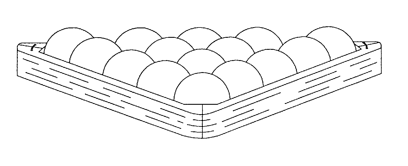
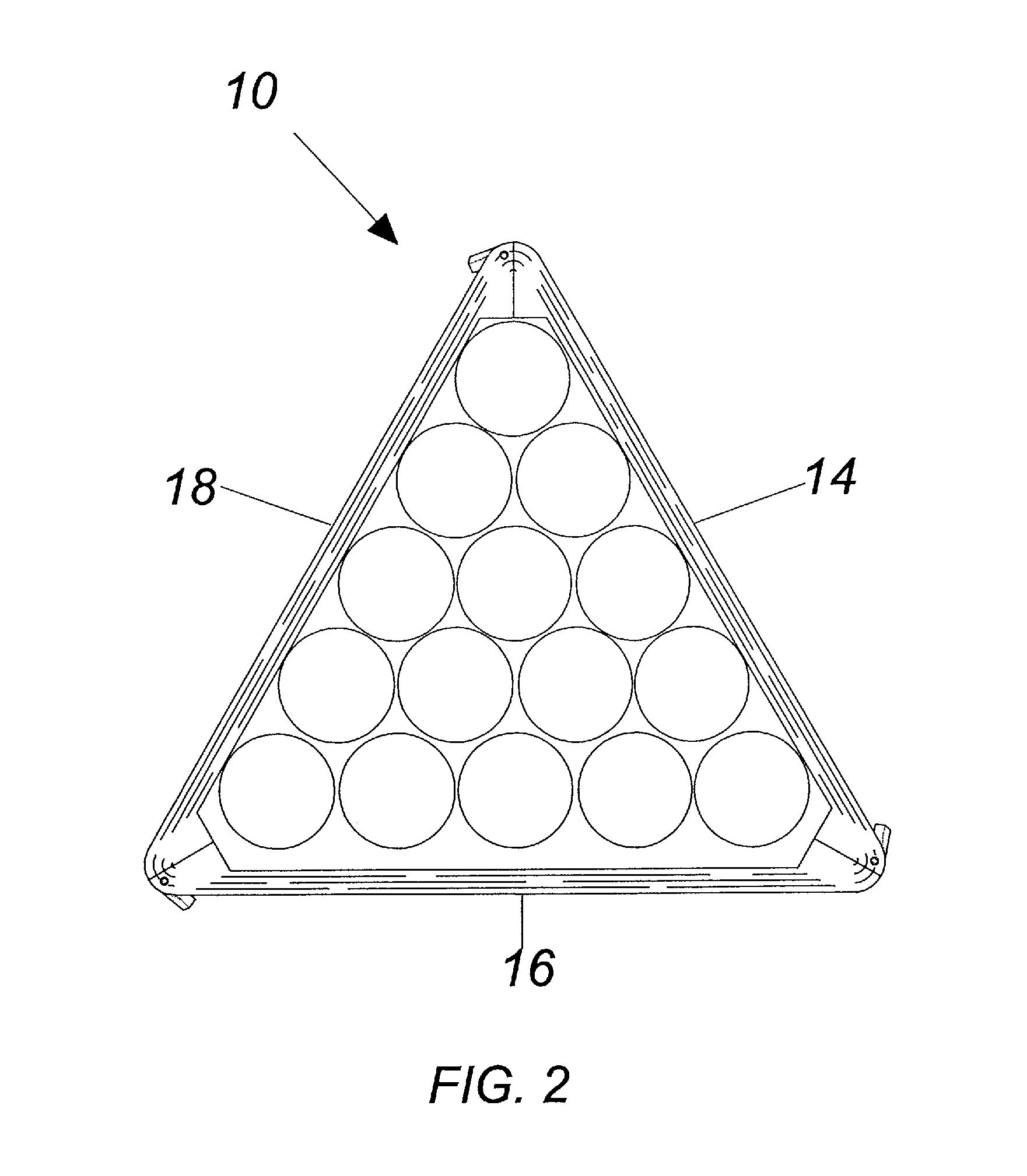
[0021]The present invention relates to a racking frame kit for use in the game of billiards, pool or snooker. In particular, the racking frame kit allows for ease of disassembly wherein the player can easily transport a racking frame kit from location to location. The racking frame kit generally comprises a frame having a plurality of relaseably attached side walls which form an opening for engaging an outer periphery of a group of billiards balls to compact them into a desired configuration.
[0022]In accordance with the present invention, there is provided a racking frame kit for arranging and compacting a group of balls into a predetermined pattern comprising a frame with a first side wall, a second side wall and a third side wall, and a means for coupling the side walls into a triangular pattern without changing of dimensional tolerances.
[0030]It is another objective of the present invention to provide an improved racking frame kit that allows for removal of said rack without disturbing the formation of playing balls.
[0031]Still another object of the present invention to provide an improved racking frame kit that will fit into a standard rack holder found in billiard halls.

Problems solved by technology

A tight grouping of ball allows for a transfer of energy between the balls whereas a loose group will allow for the quick dissipation of energy and lead to an unpredictable scatting of the balls.
Even with a skilled user, a tight pattern is not easily obtained using a conventional racking frame.
However, when the player removes their fingers from racking frame, movement of the balls may inadvertently occur.
Unfortunately, these devices often have a complicated structure and are expensive in construction.

Method used


Image

  • Racking frame kit
  • Racking frame kit
  • Racking frame kit

Examples


first embodiment

[0043]Now referring to the drawings, set forth is the instant invention consisting of a racking frame kit 10 that fits within a storage container 12. The frame kit is defined by three similarly shaped side members 14, 16, and 18, each side member having a length, width and height that is equal in size between the members. Side member 14 has a first end 20 and a second end 22 with a generally upright configuration defined by an inner surface 24 and an outer surface 26. The inner surface 24 may be inclined to assist in compressing of balls in a tighter configuration, as will be further defined. The first side member 14 is illustrated of each side member and includes a lifting lever 28 having a pivot point 30 along the second end 22 of the side member, said lifting lever including a capture point 34 which has the same axis as the pivot point 30. The first end 20 includes an attachment rod member 36 extending between a first and second tab 38, 40 extending from the first end 20.

[0044]By...

second embodiment

[0048]Referring now to FIGS. 7 and 8, set forth is second embodiment of the instant invention wherein the equilateral triangle racking frame kit 50 is formed from a first side member 52, a second side member 54, and a third side member 56. First side member 52 being illustrative of the invention having a tongue 58 along a first end 60 in a grove 62 disposed along a second end 64. The first end 60 is securable to a second end 64″ of side member 54 by placement within grove 62,″ similarly a first end 60″ having a tongue 58″ is securable to third member 36 having a second end 64′ with a grove 62′. Side member 56 is securable to adjoining side member 52 with first end 60′ having tongue 58′ securable to grove of side member 52 along end 64. The tongue and grove assembly maintains exact dimension for the player while assembled forming an equal lateral triangle pattern enclosure available for a seed of a group of balls. As with the previous embodiment, the disassembly of the individual mem...

third embodiment

[0050]Now referring to FIGS. 9 and 10, set forth is the instant invention having side members 70, 72 and 74. Side member 70 includes a first end 76 having protrusions 78, 80 placed on either side of a magnet 82. As second end 74 has receptacles 86, 88 placed on either side of an integrated metal 90 portion. Second member 72 has a first end 76′ with protrusions 78′ and 80′ placed on each side of magnet 82′ and a second end 84′ having receptacle 86′ and 88′ placed on either side of medal insert 90′. Third side member 74 has protrusion 78″ and 80″ placed on either side of magnet 82″ and second end 84″ having first receptacle 86″ and second receptacle 88″ placed on either side of metal insert 90″. The first end of side member 70 is securable to the second end of side member 72, the first end of side member 72 is securable to second end of side member 74 and first end of side member 74 is securable to second end to side member 70 there by forming the equilateral triangle enclosure for re...


PUM


Abstract

A racking frame kit including a storage container housing three shaped side members that can assembled into an equilateral triangular enclosure for receipt of a group of balls in a compressed position. The racking frame providing a portable device that allows pool players to obtain the repeatability necessary from location to location. The kit further provides for the tightening of the formation of balls to obtain the maximum transfer of energy from a cue ball impact which will allow a predictable and disperse spread of balls across a playing surface. Various embodiments include a latching release, a magnet release, a tongue & groove release, and an elastic band.

Description

FIELD OF THE INVENTION[0001]This invention is related to the field of billiards, pool and snooker play and more particularly to an improved transportable racking frame kit.BACKGROUND OF THE INVENTION[0002]In the games of billiards, pool, and snooker, playing balls are arranged in a pre-determined pattern on a flat rectangular table. Full size snooker and English billiard tables are 12 feet long. Pool halls typically have 9 foot tables and smaller halls may have 7 foot tables. The tables provide a platform for the games wherein the balls are struck with a stick for moving them around the table which is bounded by rubber cushions. Billiards is a game played without pockets. Pool is game played with six pockets, and hosting probably the most notable game known as 8-ball or pocket billiards. Snooker is technically a pocket billiards game and popular in view of its historic divergence from other games. These games all require a level of skill and are extremely popular with individuals of...

Claims


Application Information

Patent Timeline
IPC IPC(8): A63D15/00
CPCA63D15/005
Inventor KAPLAN, MATTHEW
Owner KAPLAN MATTHEW
Learn More