
Automatic vision aligned scriber

Inactive Publication Date: 2012-11-15
ORISOL ASIA
View PDF7 Cites 22 Cited by
  • Summary
  • Abstract
  • Description
  • Claims
  • Application Information

AI Technical Summary

Benefits of technology

[0009]The primary object of the present invention is aimed at solving all the abovementioned disadvantages by providing an automatic vision aligned scriber, wherein the footwear assemblies can be automatically scribed or printed by a small computerized scriber or printer without using shoe templates or silk screen. The present invention is further capable of using image to identify and locate the positions of the footwear assemblies, so that the patterns or stitch marks can be printed or scribed at accurate positions on the respective footwear assemblies, without having to make the footwear assemblies precisely fixed on the printing surface. The printing or scribing is performed by an inkjet printer which includes a flat table and a printing head mounted on a manipulator, and the manipulator is capable of moving the printing head along the path which covers the entire area of the table.
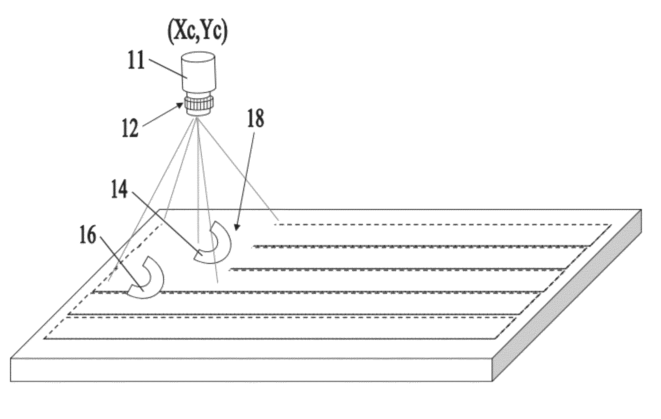
[0020]The automatic vision aligned scriber in accordance with the present invention further includes an image processor which is provided with a digital camera, an image processing computer and an image analysis software. The digital camera is assembled to the movable printing head. Before printing, when the footwear assemblies are positioned at any arbitrary positions on the table, the camera takes a set of images covering the entire area of the table. The images are processed by the image processing computer. Define the geometries of all the footwear assemblies and the relation between the geometries of all the footwear assemblies and the stitch marks, the image analysis software can identify the respective footwear assemblies based on their unique geometry parameters, and the locates the position and orientation of the footwear assemblies based on the positions of the geometries of the footwear assemblies. Finally, the image analysis software can move or change the stitch marks to fit the arbitrary positions of the footwear assemblies. When all the patterns and stitch marks are reset, patterns will be printed with tiny drops of ink at the final position at which the geometry patterns need to be printed.
[0023]To better understand how the present invention overcomes the disadvantages of the conventional art, the geometry data of the present invention is digital. Therefore, the present invention doesn't need to use shoe templates or silk screens, and according doesn't require a large area to store the hundreds of templates. Furthermore, the printing device is as small as an office desk, and the printing device can be operated by only a single operator and has a capacity same as the workload of several operators using conventional methods. Therefore, the present invention is truly labor-saving, as compared to the conventional method that requires the footwear assemblies to be put at precise positions in a large ground area, and then the footwear assemblies are manually marked one by one by using a template.

Problems solved by technology

Both of the above methods are labor intensive due to the fact that it is time-consuming to put the shoe template or the silk screen precisely at the designated positions on the footwear assemblies.
However, it still costs a lot of time to prepare the precise positions of the respective footwear assemblies on the table and to adjust the positions of the blocks with respect to the footwear assemblies.
Bad consequence will occur if want to save time.
Marking the stitch mark with the above methods requires the factory to have a large area for many tables loaded with many footwear assemblies, thus increasing the cost of purchasing real estate.
Another disadvantage is that it needs to produce various shoe templates or silk screens for the respective footwear assemblies of different sized left and right shoes.
Any style of shoes may involve the use of hundreds of templates, which not only increases the production cost, but requires a large warehouse to store the templates.
Moreover, picking out the needed templates from the sea of templates may also cause cost increase.
A third disadvantage is that the above methods need to be carried out in a hall (big room) of a factory, namely, all the footwear assemblies required for making shoes must flow through the hall, which contradicts the notion that it should try to minimize inventory and use flexible slanting production line during production.

Method used


Image

  • Automatic vision aligned scriber
  • Automatic vision aligned scriber
  • Automatic vision aligned scriber

Examples


Embodiment Construction

[0028]The present invention will be clearer from the following description when viewed together with the accompanying drawings, which show, for purpose of illustrations only, the preferred embodiment in accordance with the present invention.

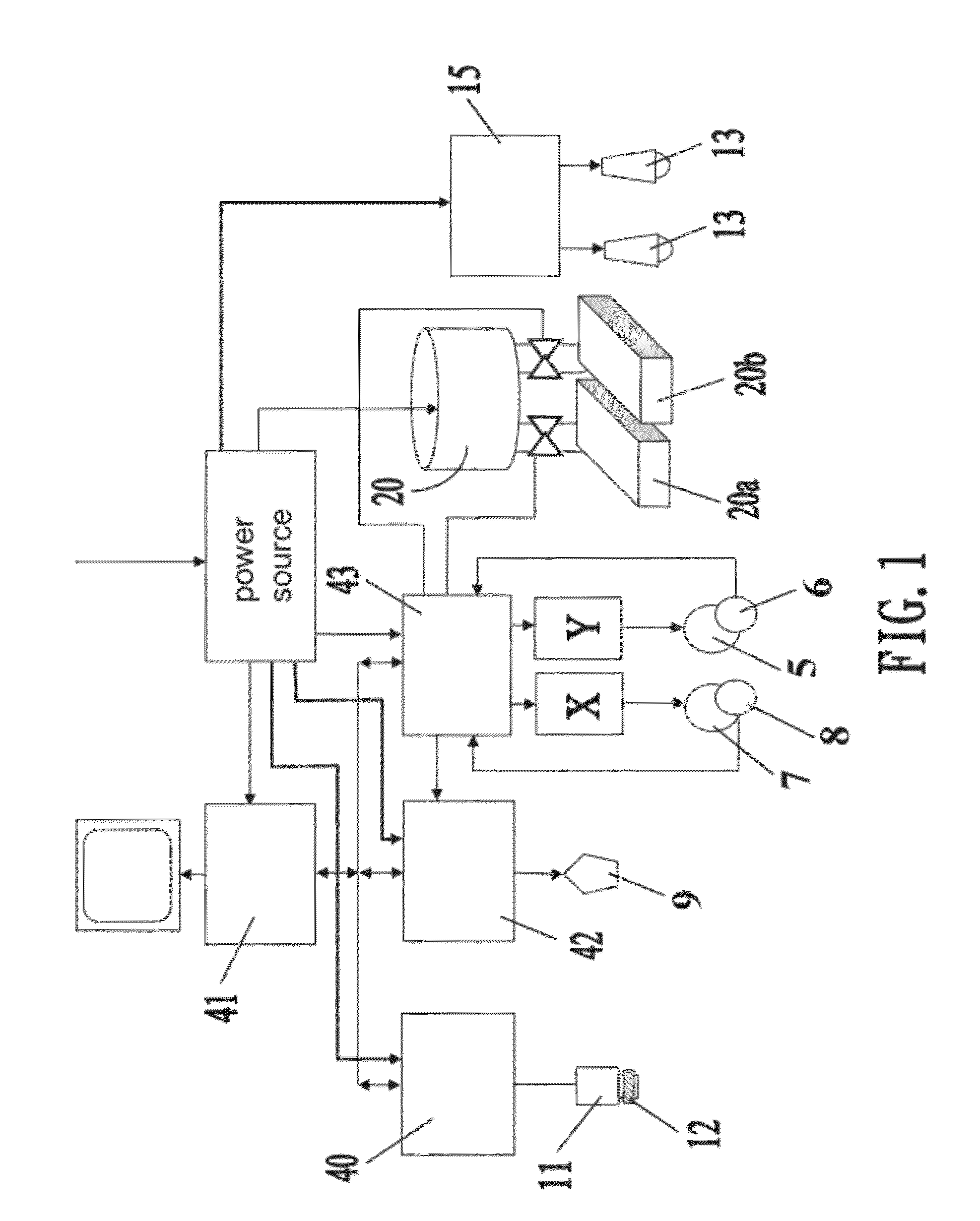
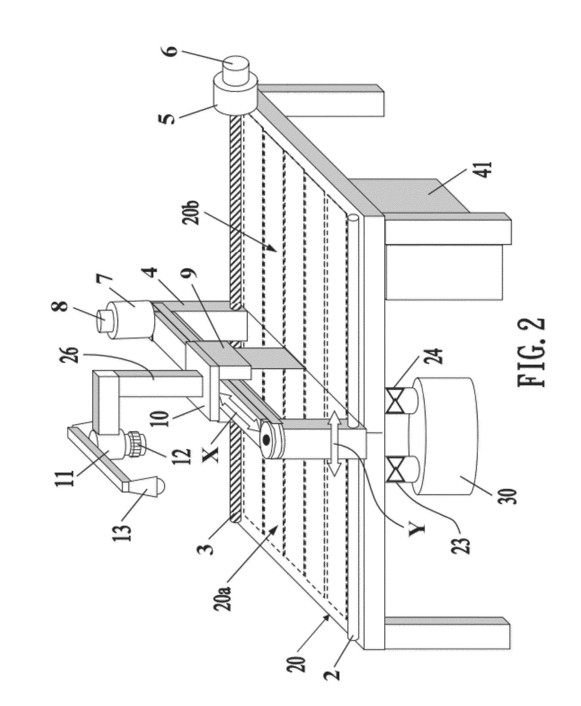
[0029]Referring to FIGS. 1-4, an automatic vision aligned scriber in accordance with the present invention includes a table 20, an adsorption orientation device, a bridge 4, a moving platform 10, a service controller 43, a printing head 9, a camera 11, a lamp 13 and an image processor 40.

[0030]The table 20 is used to carry the footwear assemblies 14 and 16, which are adsorbed to the table 20 by the adsorption orientation device (such as a vacuum pump 30) and wait to be printed, as shown in FIG. 2.

[0031]The printing head 9 is assembled to the moving platform 10, and the moving platform 10 is movably mounted on the bridge 4 and capable of moving in the direction Y together with the bridge 4 and further capable of sliding along the bridge 4 to move ...


PUM


Abstract

An automatic vision aligned scriber includes a table, an adsorption orientation device, a bridge, a moving platform, a service controller, a printing head, a camera, a lamp and an image processor. The scriber uses a flat table for placing each footwear assembly waiting for scribing. An image system can identify each footwear assembly and measure its position and orientation on the table. A manipulator is used for controlling the printing head to move above the table and printing the lineation on each footwear assembly according to its special position and orientation relative to the table. The scriber has the advantages of digitalization and space saving.

Description

BACKGROUND OF THE INVENTION[0001]1. Field of the Invention[0002]The present invention relates to a scriber, and more particularly to a digital and compact automatic vision aligned scriber.[0003]2. Description of the Prior Art[0004]When making shoes, basically, the respective parts (footwear assemblies) of a shoe should be printed or scribed with marks before being assembled together. For example, the respective footwear assemblies of the shoe are printed with logos, patterns or stitch marks along which the respective footwear assemblies are to be assembled together. These printed stitch marks instruct the sewer to sew or glue the footwear assemblies together by following the sew lines, and the printed patterns show the sewer where to sew the decorative pattern (at what position on the footwear assemblies the decorative pattern should be sewn). Currently, there are two methods for scribing a stitch mark, one of the methods is to prepare a slotted template, then put the template at a ...

Claims


Application Information

Patent Timeline
IPC IPC(8): H04N7/18
CPCA43B3/0084A43D2200/60A43D8/30A43D8/16A43D8/26
Inventor MAKOVER, JAKOVMARDLX, BAR COCHVASADEH, YAACOV
Owner ORISOL ASIA
Learn More