
Controlled gravity feed shelf system

a shelf system and gravity technology, applied in the field of shelves, can solve the problems of product not being able to pass the front edge, product not being able to feed forward, and being difficult to restock and/or remove products from shelves,

Inactive Publication Date: 2012-11-15
L A DARLING
View PDF30 Cites 67 Cited by
  • Summary
  • Abstract
  • Description
  • Claims
  • Application Information

AI Technical Summary

Benefits of technology

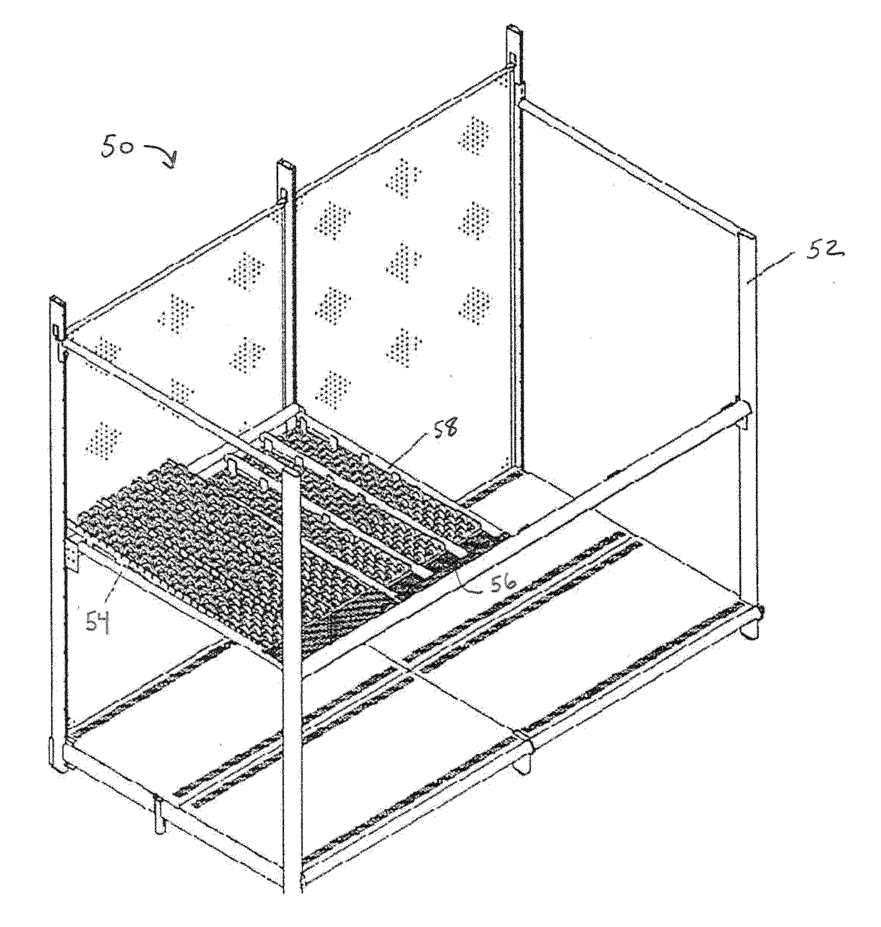
"The present invention is a controlled gravity feed shelf system that solves problems with previous gravity feed shelf systems. The system features shelf inserts with rollers that control the feed of products placed thereon. The rollers are sized to prevent products from stopping or falling off the shelf. The system also includes a retail gondola framework upon which the shelf inserts are mounted. The shelf inserts provide a combination of larger diameter rollers at the rear of the shelf to consistently initiate the forward motion of products stocked on the shelves and smaller diameter rollers on the forward portion of the shelf to slow products as they approach the front of the shelf. The front portion of the shelf has small diameter rollers to provide greater rolling resistance as products feed forward on the shelf. The rear portion of the shelf contains large diameter rollers to prevent products from falling off the shelf. The rollers are removable and can be swapped in and out depending on the product size, weight, and other details of the application. The system allows for custom tailoring for the specific application without the need to purchase entirely new shelf inserts."

Problems solved by technology

In these prior art systems, however, products may either fail to feed forward or feed forward so quickly that stops are required to prevent the product from passing the front edge of the shelf.
These stops can make it difficult to restock and / or remove products from the shelves.
In addition, a number of prior art shelf systems use fairly complex pusher mechanisms to move stocked items to the front of the shelf.
Unfortunately, when the stocked products get further than 24″ from the front edge of the shelving system, most consumers cannot reach the stock remaining on the shelf resulting in the possibility of lost sales.

Method used


Image

  • Controlled gravity feed shelf system
  • Controlled gravity feed shelf system
  • Controlled gravity feed shelf system

Examples


Embodiment Construction

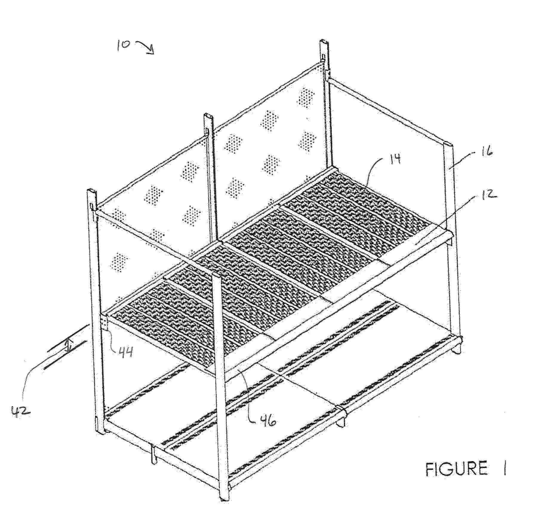
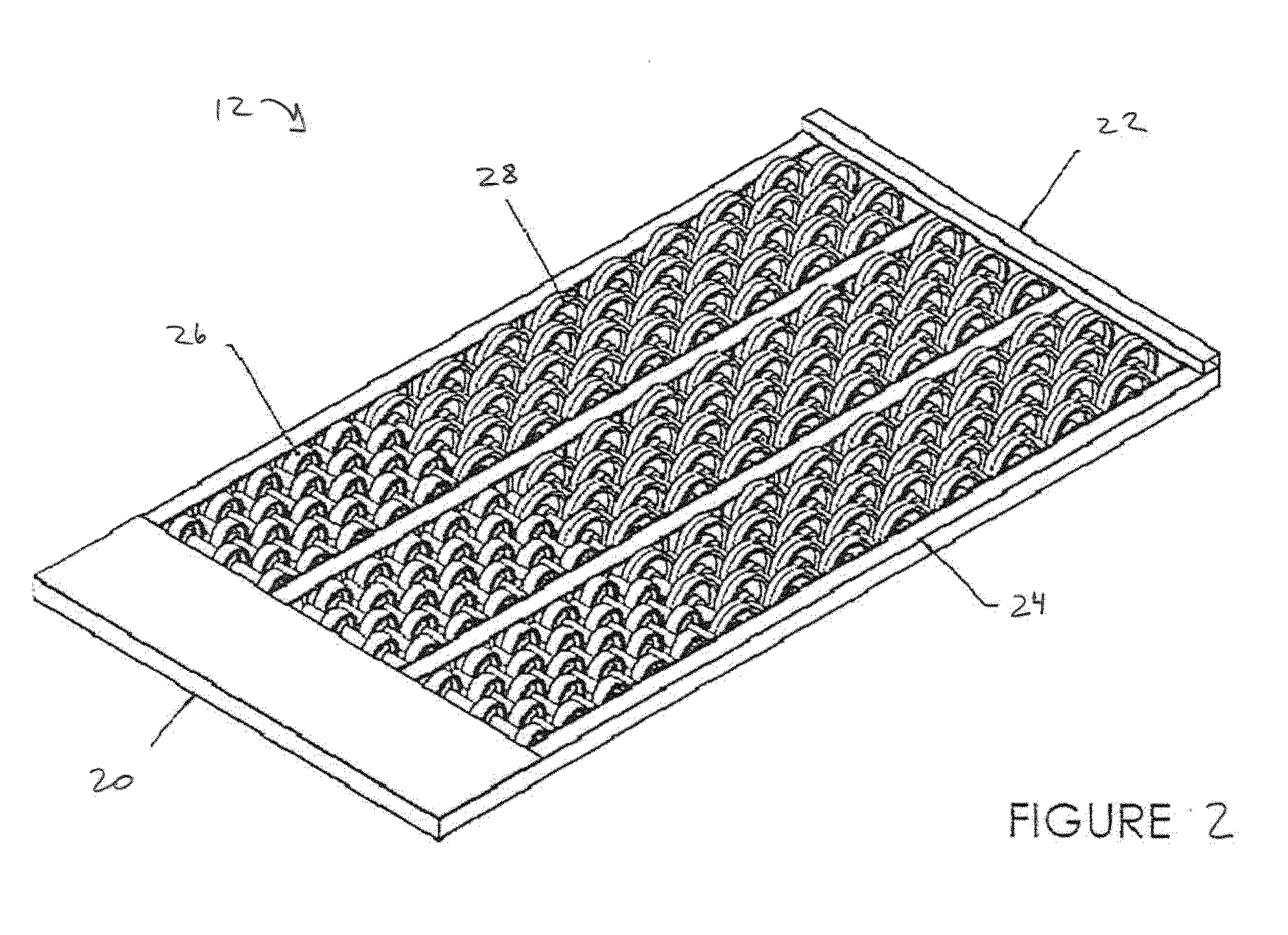
[0012]An embodiment of the controlled gravity feed shelf system of the present invention is indicated in general at 10 in FIG. 1. The gravity feed shelf system 10 features a number of shelf inserts 12 that, as explained in greater detail below, feature a roller surface 14 with rollers sized to control the feed of products placed thereon. The system includes a retail gondola framework 16 upon which the shelf inserts 12 are mounted. While FIG. 1 shows four separate inserts mounted on the gondola framework, any alternative number of the inserts featuring alternative sizes may be used instead.

[0013]In accordance with the present invention, for an applied load (product weight), a larger diameter roller will feed products more consistently than a smaller diameter roller at reduced shelf angles. The shelf inserts 12 of the present invention each provide a combination of larger diameter rollers at the rear of the shelf to consistently initiate the forward motion of products stocked on the s...


PUM


Abstract

A controlled gravity feed shelf system features a framework and at least one insert. The insert includes a number of support rails at least partially forming a front portion of the insert and a rear portion of the insert. A number of first rollers are rotatably mounted on the front portion of the insert, where each of the first rollers has a first diameter. A number of second rollers are rotatably mounted on the rear portion of the insert, where each of said second rollers has a second diameter. The first diameter of the first rollers is smaller than the second diameter of the second rollers. The insert is positioned within the framework so as the rear portion of the insert is positioned vertically higher than the front portion of the insert.

Description

CLAIM OF PRIORITY[0001]This application claims priority to provisional patent application No. 61 / 423,398, filed Dec. 15, 2010, currently pending.FIELD OF THE INVENTION[0002]The present invention generally relates to shelving systems and, more particularly, to a controlled gravity feed shelf system.BACKGROUND OF THE INVENTION[0003]Gravity feed shelf systems are well known. Such systems typically feature inclined shelves and are useful for dispensing products ranging from two-liter beverage bottles to automotive batteries to cans of soup and the like. Examples of prior art gravity feed shelf systems are presented in U.S. Pat. No. 6,267,258 to Wilkerson et al. and U.S. Pat. No. 4,715,765 to Agnoff. In these prior art systems, however, products may either fail to feed forward or feed forward so quickly that stops are required to prevent the product from passing the front edge of the shelf. These stops can make it difficult to restock and / or remove products from the shelves. Additionally...

Claims


Application Information

Patent Timeline
Patent Type & Authority Applications(United States)
IPC IPC(8): A47F1/04
CPCA47B96/021B65G1/023A47F5/0043A47F1/12
Inventor O'QUINN, TAFTMARTIN, MICHAELMARTIN, CARRIEDUCHENE, VAL-JEAN
Owner L A DARLING
Learn More