
Wheelchair Device

a technology for wheelchairs and wheelchairs, applied in the field of wheelchair devices, can solve the problems of inefficiency and hard propelling, and achieve the effect of convenient control and less for

Inactive Publication Date: 2012-10-25
JOO YOUNG HAN
View PDF16 Cites 3 Cited by
  • Summary
  • Abstract
  • Description
  • Claims
  • Application Information

AI Technical Summary

Benefits of technology

The new wheelchair device has two main benefits - it's easier to operate and control compared to traditional devices. It also prevents certain parts from coming loose or getting damaged during use.

Problems solved by technology

The technical problem addressed in this patent is the difficulty and efficiency of traditional wheeled chair devices where users must push on hand rims with strong arms while trying to maintain balance. There is also a lack of space between the hands and feet when wearing shoes or other footwear.

Method used


Image

  • Wheelchair Device
  • Wheelchair Device
  • Wheelchair Device

Examples


Embodiment Construction

[0068]The Provisional U.S. Patent Application Ser. No. 61 / 478,010 is incorporated by reference into this disclosure as if fully set forth herein.

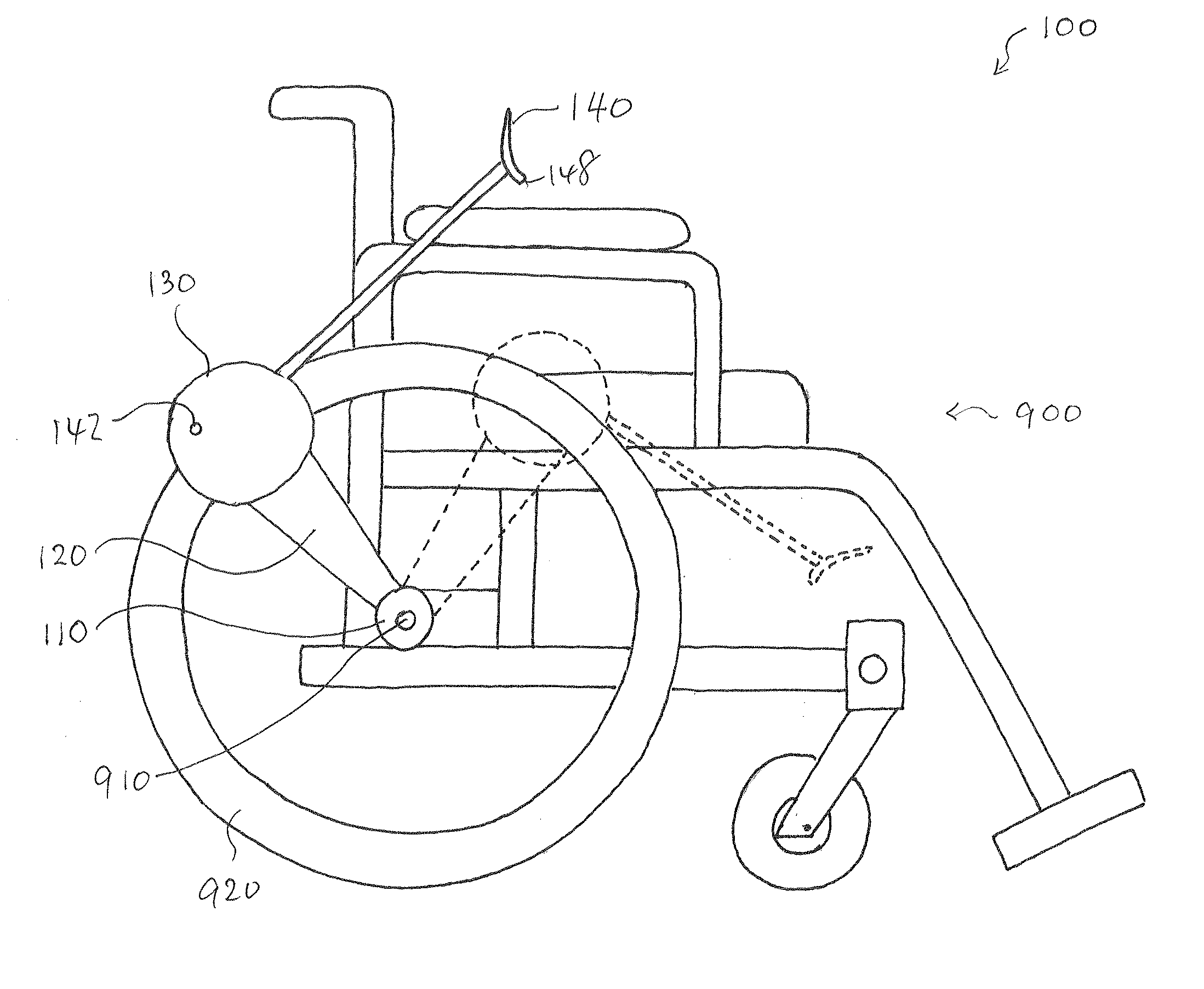
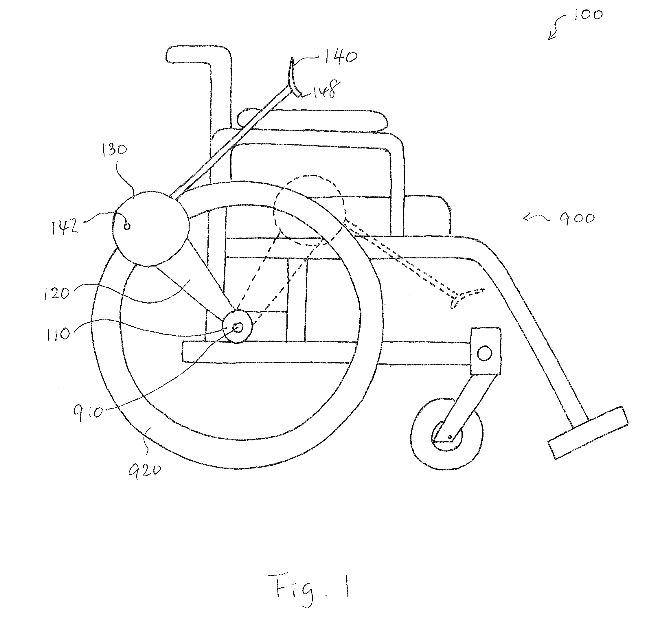
[0069]FIGS. 1-4 show a wheelchair device 100 according to an embodiment of the present invention.

[0070]An aspect of the invention provides the wheelchair device 100.

[0071]The wheelchair device 100 comprises:

[0072]a hub-supporting disc 110 engaging a hub 910 disposed in a wheel 920 of the wheelchair 900 rotatably;

[0073]an arm 120 extending from the hub-supporting disc 110 toward a tube portion of the wheel 920;

[0074]an outer disc 130 fixed to an end of the arm 120; a power handle 140 engaging the outer disc 130 with a hinge 142 hooked at an axle fixed to the outer disc 130 rotatably, and the hinge 142 is disposed at a position close to an end of the power handle 140;

[0075]a rear wheel-holding protrusion 144 extending inward from an end of the power handle 140; and

[0076]a front wheel-holding protrusion 146 extending inward from a position opp...


PUM


Abstract

A wheelchair comprises a hub-enclosing open ring engaging a hub disposed in a wheel rotatably, bars extending from two ends of the hub-enclosing open ring, an crescent-shaped cap member fixed to the bars above the tube portion, a power handle engaging the crescent-shaped cap member rotatably through an L-shaped end of the power handle, a wheel-holding plate fixed to the power handle with an angle and covered by the crescent-shaped cap member. The wheel-holding plate comprises a holding edge for pressing down on and holding the wheel. The hub-enclosing open ring, the bars, and the cap member are fixed to one another and configured to rotate about the hub, and the holding edge of the wheel-holding pate is configured to be pressed down on and engaged firmly to the wheel such that the wheel rotates about the hub by pushing and pulling the power handle.

Description


Claims


Application Information

Patent Timeline
Owner JOO YOUNG HAN
Learn More