
Mechanical seal device

a mechanical seal and sealing fluid technology, applied in the direction of engine seals, mechanical apparatus, engine components, etc., can solve the problems of complicated constitution of the whole seal device, easy leakage of sealing fluid from the dividing face, and insufficient time for exchange process, etc., to achieve the effect of appropriate sealing ability

Inactive Publication Date: 2012-10-04
EAGLE INDS
View PDF19 Cites 1 Cited by
  • Summary
  • Abstract
  • Description
  • Claims
  • Application Information

AI Technical Summary

Benefits of technology

[0015]The present invention was accomplished by reflecting such problems, and its object is to provide a divisional type mechanical seal device of an outside type, capable of maintaining the connecting part of the seal face always accurately in flat even in the seal ring having a complicated shape such as those having a portion with different thickness in the radial direction, and also capable to exhibit a appropriate sealing ability, while the constitution is simple and inexpensive.Means for Solving the Technical Problems
[0017]According to the mechanical seal device of the present invention having such constitution, the O ring is placed so that it corresponds to the portion having a different radial direction thickness of the seal ring thereby the seal ring is pressed from the outside; thus even if the seal ring undergoes complicated deformation due to the difference of the thickness in the radial direction, the O ring placed at each parts (area) can provide an appropriate tension force to the portion (area) thereof, and can appropriately suppress or prevent the deformation. As a result, the connecting part of the seal face is always maintained accurately in flat, maintain the divisional type mechanical seal appropriately in a ring form, and can exhibit the appropriate sealing ability. Also, the mechanical seal device which is inexpensive and having simple constitution can be provided.
[0019]According to the mechanical seal of the present invention having such constitution, even when joining the dividing faces of the divisional type holder, it is fasten by the individual fastening bolts against the portion having a different thickness in the radial direction of the seal ring, thus further appropriate tension force can be provided by each portion (area) to the deformation caused by the difference of the thickness in the radial direction of the seal ring, and also the seal ring can be maintained in a ring shape appropriately. As a result, the connecting part of the seal face can be always maintained accurately in flat, the divisional type mechanical seal is maintained in ring form appropriately, and can exhibit a appropriate sealing ability.
[0021]According to the mechanical seal of the present invention having such constitution, at the dividing faces of the divisional holder, the end faces of each divisional parts do not contact closely against each other, thus it is joined so that a slight space is formed therebetween, thereby due to the fastening force of the connecting means of the fastening bolts or so, the pressing force and the tension force acting on the outer peripheral of the seal ring placed at the inner peripheral side can be controlled. As a result, the connecting part of the seal face can be maintained always accurately in flat, and the divisional type mechanical seal is maintained in ring form appropriately, and can exhibit an appropriate sealing ability.
[0023]According to the mechanical seal device of the present invention having such constitution, the contacting area between the outer peripheral of the seal ring and the O ring is increased and the compression force acting on the O ring can be reflected to the tension force in full extent, further it also enables to make the O ring and the seal ring as an one body in the axial direction. As a result, the axial direction position of the seal ring can be appropriately controlled by a simple constitution, and also it can be maintained strongly in a condition that the dividing faces are joined, further even if the sealing fluid is a high pressure fluid or so, an appropriate sealing ability can be exhibited.
[0025]According to mechanical seal device of the present invention having such constitution, the seal ring and the holder is further secured as an one body via the O ring, thus the pressing force from the holder can be reflected to the tension force in full extent, and also the holder and the seal ring can be made into one body in both the axial direction and the circumference direction. As a result, the axial direction position and the circumference direction position of the seal ring can be further appropriately controlled, and also the condition in which the dividing faces are joined can be maintained strongly, further even if the sealing fluid is a high pressure fluid, an appropriate sealing ability can be exhibited.

Problems solved by technology

Conventionally, as for the mechanical seal used in a fluid transport machine (the transport device), when the transport machine is large, exchange process took too much time and was also costly.
In regards with the divisional type mechanical seal, generally, when a pressure of a sealing fluid is applied to the inner diameter side of the seal ring which cannot be fixed by the bolts or so, the pressure thereof acts in a direction to open dividing faces of the sealing ring, which causes the sealing fluid to easily leak from the dividing faces.
However, as for the mechanical seal of the inside type, the sealing fluid is present at the outside of the seal ring, thus a seal cover is necessary, which causes the problem that the constitution of the whole seal device becomes complicated.
However in this method, due to the difference of the heat expansion coefficient between the fastening ring made of metals and the seal ring (generally, the heat expansion coefficient of the metals are larger than that of the sealing ring), either one of the fastening ring or the seal ring, or both of those may be deformed or loosened.
However, in this method, when the deformation to the seal ring is caused by the heat or pressure, the dividing faces in parts where the elasticity of the elastic member does not reach may open.
Particularly, when the seal ring does not have a form of a ring shape of a simple rectangular cross section, the deformation may be caused due to the difference of the thickness between the thinner portion and the thicker portion; however in such method it cannot handle such deformation.
However, this is a method in which the dividing faces of the seal ring are pressed by the tension force of the elastic body provided at a portion in the axial direction of the outer peripheral of the seal ring; therefore it can only deal with the seal ring having a simple shape like cylinder.
Also, as it only comprises the elastic means at the outer peripheral face, it cannot deal with the displacement of the dividing faces in the axial direction.
However, such elastic member having a shape which covers the entire peripheral face of the seal ring basically needs to be prepared for each seal ring due to the difference of the diameter of the seal ring or so, thus the production cost becomes high, and as a result the price as the specialized parts becomes expensive.
Also, it becomes complicated to manage the parts.
Moreover, further specifically, it is necessary to produce a specialized mold in order to produce such a specialized elastic member, and the management of the mold is too much of a work.

Method used


Image

  • Mechanical seal device
  • Mechanical seal device
  • Mechanical seal device

Examples


Embodiment Construction

[0032]The mechanical seal device of one embodiment of the present invention will be described by referring to FIG. 1 to FIG. 4.

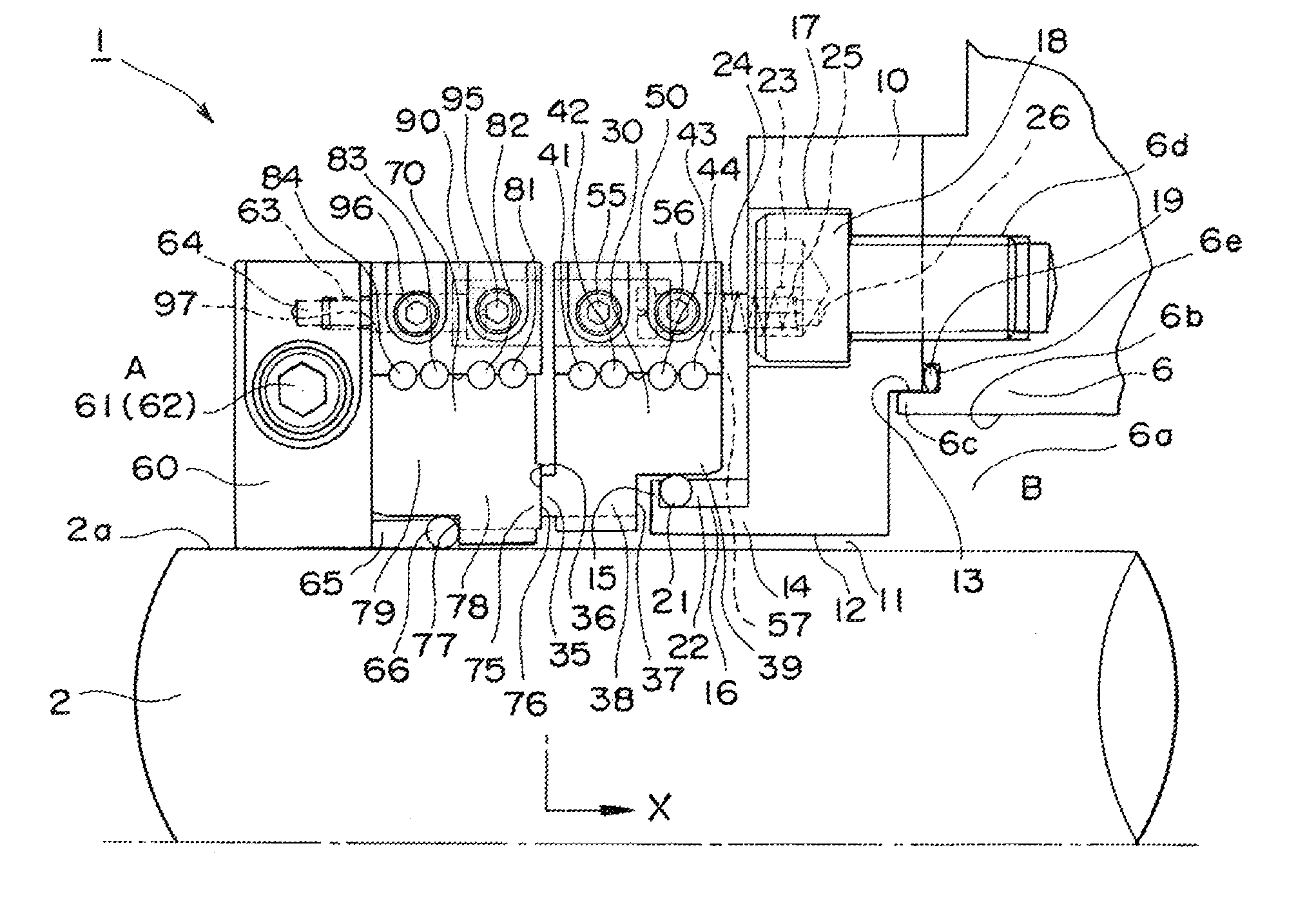
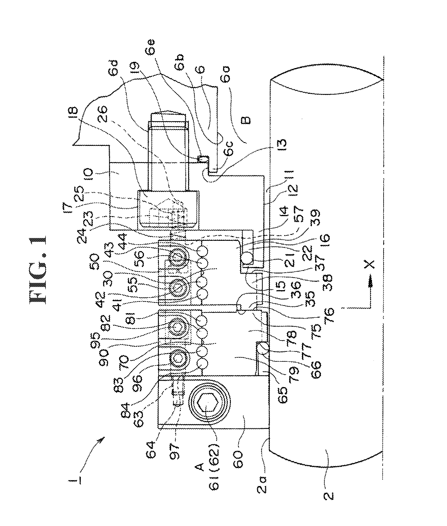
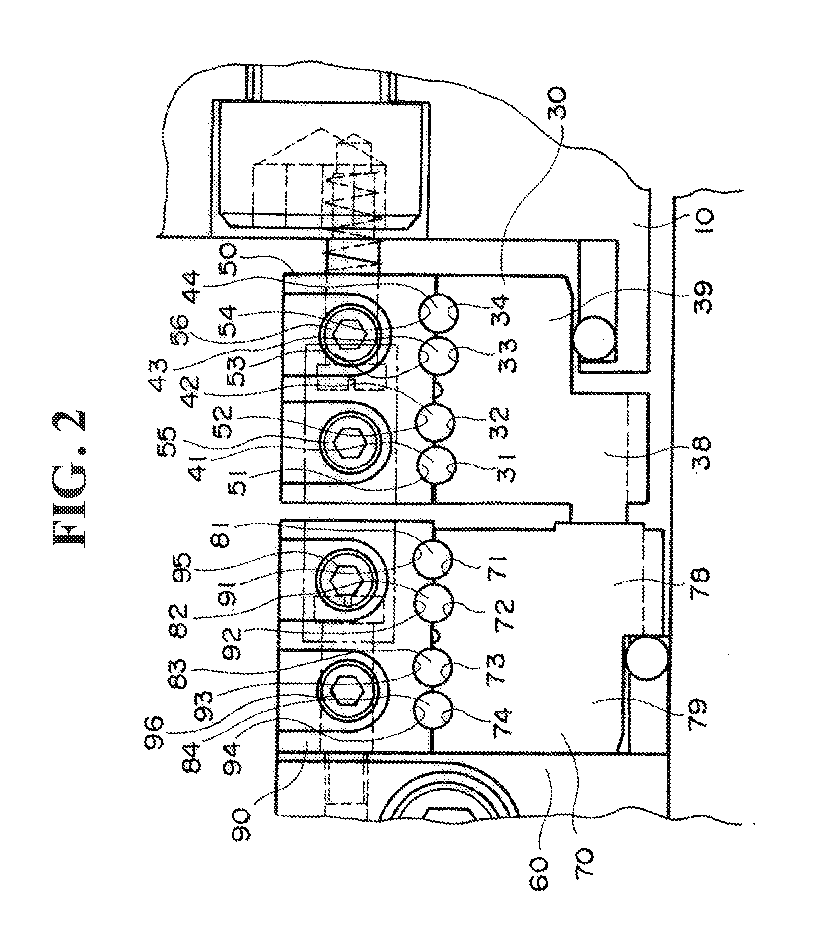
[0033]FIG. 1 shows a cross sectional figure in the axial direction showing the constitution of the mechanical seal device of the present embodiment, and FIG. 2 is an enlarged view nearby the stationary ring (seal ring) 30 and the rotational ring (mating ring) 70 of the mechanical seal device 1. FIG. 3 is a cross sectional figure in the axial direction at X position of FIG. 1, and FIG. 4 is a front view figure of a collar 60 of the mechanical seal device shown in FIG. 1.

[0034]The mechanical seal device 1 of the present embodiment is a divisional type mechanical seal of the outside type. As shown in FIG. 1, the mechanical seal device 1 comprises, as main constitutional parts, a flange 10, a stationary ring (seal ring) 30, O rings 41 to 44, a stationary ring fixing holder 50, a collar 60, a rotational ring (mating ring) 70, O rings 81 to 84, and a rotational ri...


PUM


Abstract

The object of the present invention is to provide a divisional type mechanical seal of outside type which joins the seal face in flat and strongly even in a seal ring having a different thickness in the radial direction, and to exhibit an appropriate sealing ability. In the mechanical seal device of the present invention, the circumference grooves 31 to 34 and 71 to 74 are formed in correspondence with the thicker area 38 and 78 and the thinner area 39 and 79 at the outer peripheral face of the seal ring 30, 70; and the circumference grooves 51 to 54 and 91 to 94 are formed in correspondence with the circumference direction grooves 31 to 34 and 71 to 74 at the inner peripheral face of the holder 50 and 90. By placing the O rings 41 to 44 and 81 to 84 in between the circumference grooves 31 to 34 and 71 to 74 of the seal ring 30 and 70, and the circumference grooves 51 to 54 and 91 to 94 of the holder 50 and 90, the holder having a ring shape of which the divisional parts of each holder is joined by the bolts 55, 95 and 56 and 96 respectively corresponding to the thicker area 38, 78 and thinner area 39, 79; each divisional parts of the divided seal ring can be strongly joined and the each seal ring 30 and 70 are formed in ring shape.

Description

TECHNICAL FIELD[0001]The present invention relates to a mechanical seal device, and particularly to a divisional type and outside type mechanical seal device.BACKGROUND ART[0002]Conventionally, as for the mechanical seal used in a fluid transport machine (the transport device), when the transport machine is large, exchange process took too much time and was also costly. Thus, the structure was proposed which enables to divide the mechanical seal so that it can be exchanged without disassembling the transport machine, which is already in practical use (for example, refer to FIG. 1 of PCT publication WO2007 / 136453 (Patent document 1)).[0003]In regards with the divisional type mechanical seal, generally, when a pressure of a sealing fluid is applied to the inner diameter side of the seal ring which cannot be fixed by the bolts or so, the pressure thereof acts in a direction to open dividing faces of the sealing ring, which causes the sealing fluid to easily leak from the dividing faces...

Claims


Application Information

Patent Timeline
Patent Type & Authority Applications(United States)
IPC IPC(8): F16J15/38
CPCF16J15/3488
Inventor SUEFUJI, YOSHIHIRO
Owner EAGLE INDS
Learn More