
Method To Detect Firmware / Software Errors For Hardware Monitoring

a hardware monitoring and firmware technology, applied in error detection/correction, instruments, computing, etc., can solve problems such as increased repair and replacement costs, labor, repair time and warranty-related costs, and loss of customer confiden

Inactive Publication Date: 2012-09-20
IBM CORP
View PDF10 Cites 36 Cited by
  • Summary
  • Abstract
  • Description
  • Claims
  • Application Information

AI Technical Summary

Benefits of technology

[0008]One aspect of the present invention is directed to a system or method that uses more than one list of fault conditions, including at least the following: (i) a first list of fault conditions as detected under the current version of the non-hardware; and (ii) a second list of fault conditions as detected under the previous version of the non-hard-ware. In some embodiments, this use of multiple fault lists will be used in conjunction with the fact that the hardware is constant with respect to both the first and second fault lists in order to identify a detected problem as a non-hard-ware problem rather than as a hardware problem. Accurately identifying the root cause of problem as a non-hard-ware problem, rather than a hardware problem, can save diagnostic effort, repair time and warranty-related costs.
[0011]In some embodiments, the new firmware can supply a list of new hardware errors that are being monitored. In these embodiments, the new errors can be removed from the list in the comparison as it is expected that the older software / firmware was not capable of producing that error. In these embodiments, one goal is to improve hardware monitoring and take into account that the previous version did not provide that level of monitoring. Thus, some embodiments according to the present invention include software / firmware that can detect new hardware failures so that these are not going to be misinterpreted as coding bugs.
[0014]In some embodiments of the present invention, when a non-hard-ware update is about to be performed, the error reporting code may cause the about-to-be-replaced version of the non-hard-ware run one last time so that the first list can be generated, and later compared to the second list. In these embodiments, the update to software and / or firmware would be made after the about-to-be-replaced non-hard-ware does its last “diagnostic” run and the first list is obtained. This method has the advantage that it is unlikely that the hardware configuration would change between the last “diagnostic” run of the previous non-hard-ware and the initial run of the newly-updated software. The firmware could automatically, or at operator request, perform validation step by rerunning the previous version of software or firmware generating a list for a second time on the old and new software or firmware. An option can be added to keep the user on the old software or firmware and report the new problem to support.

Problems solved by technology

The present invention recognizes that this unnecessary replacement increases repair and replacement costs and can eventually cause a loss of customer confidence.
Accurately identifying the root cause of problem as a non-hard-ware problem, rather than a hardware problem, can save diagnostic effort, repair time and warranty-related costs.
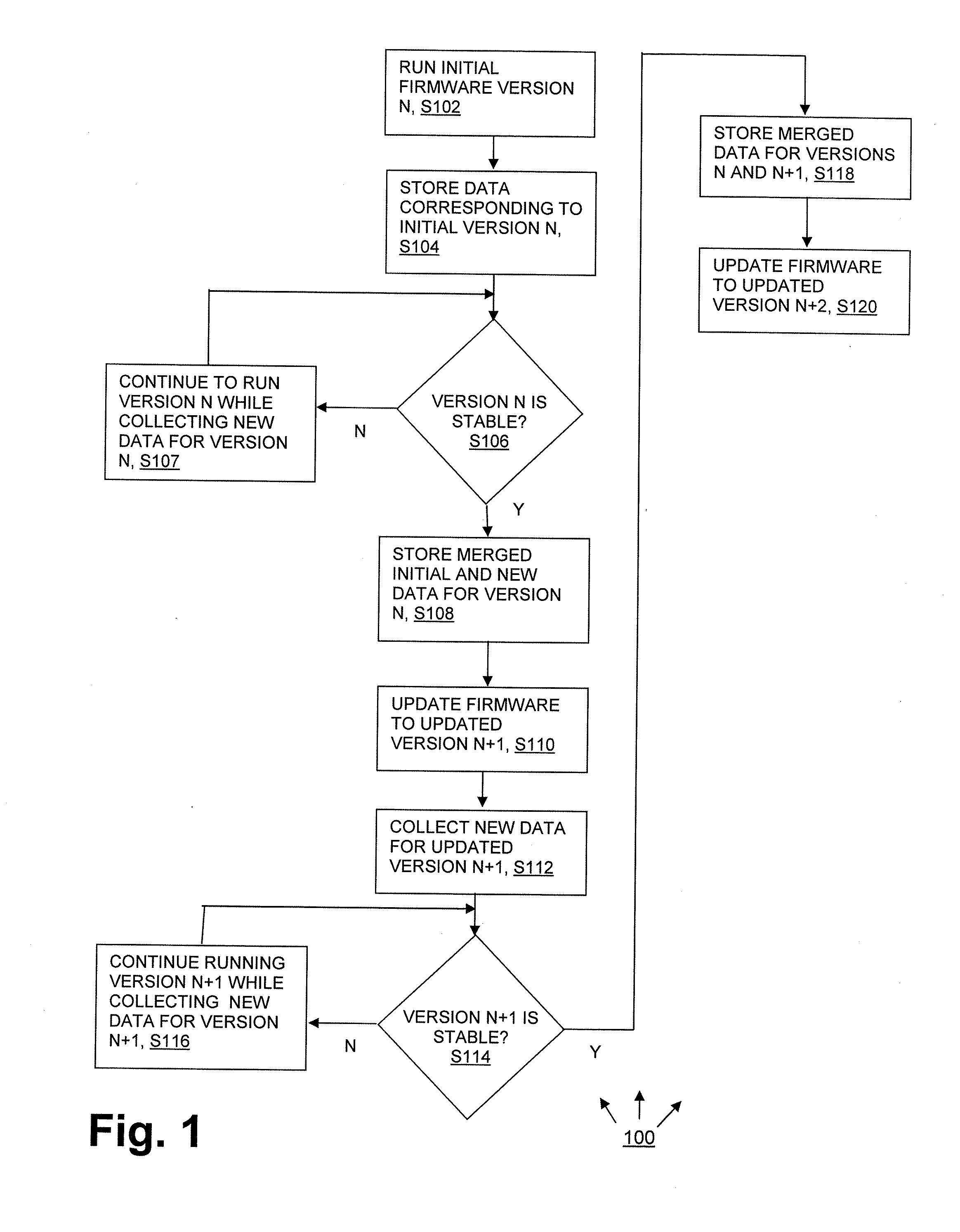
Once the second list is deemed stable, such as after a predefined learning period has passed, and the hardware configuration is known to have remained constant, then the new problems that are on the second list, but not on the first list will be identified by the error reporting code as non-hardware-problems (that is, software problems, firmware problems).
More specifically, a latent hardware problem occurs when a new version of the software relies upon hardware resources that the previous version did not rely upon, and it turns out that those particular hardware resources are subject to a hardware problem.
For example, this sort of latent hardware problem could be implicated where a reboot or reset accompanies an update.
The problems that are on the second list, but not on the first list, are candidates for software or firmware errors rather than hardware errors, especially if it is known with confidence that the hardware configuration has not changed.

Method used


Image

  • Method To Detect Firmware / Software Errors For Hardware Monitoring
  • Method To Detect Firmware / Software Errors For Hardware Monitoring
  • Method To Detect Firmware / Software Errors For Hardware Monitoring

Examples


Embodiment Construction

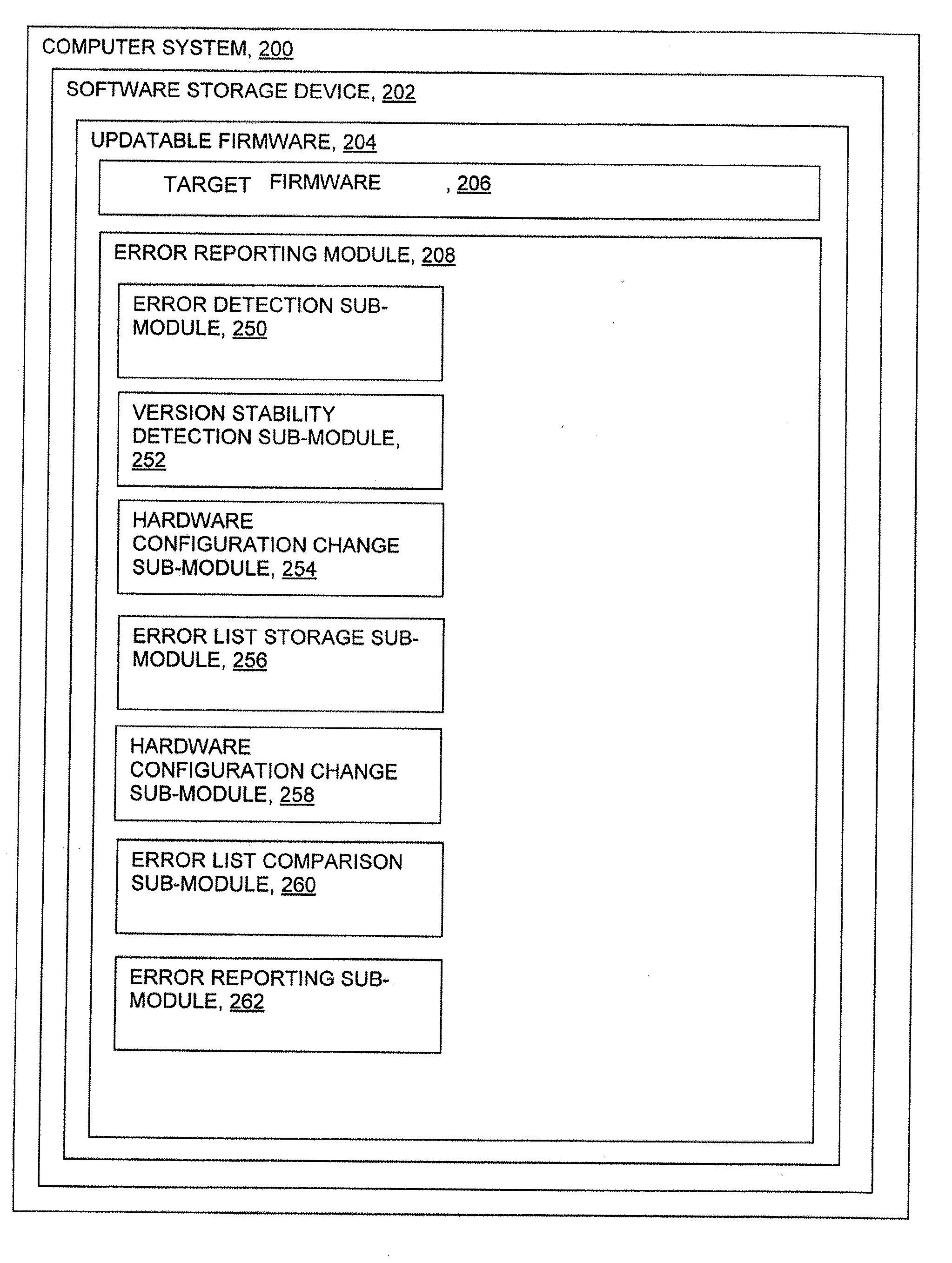
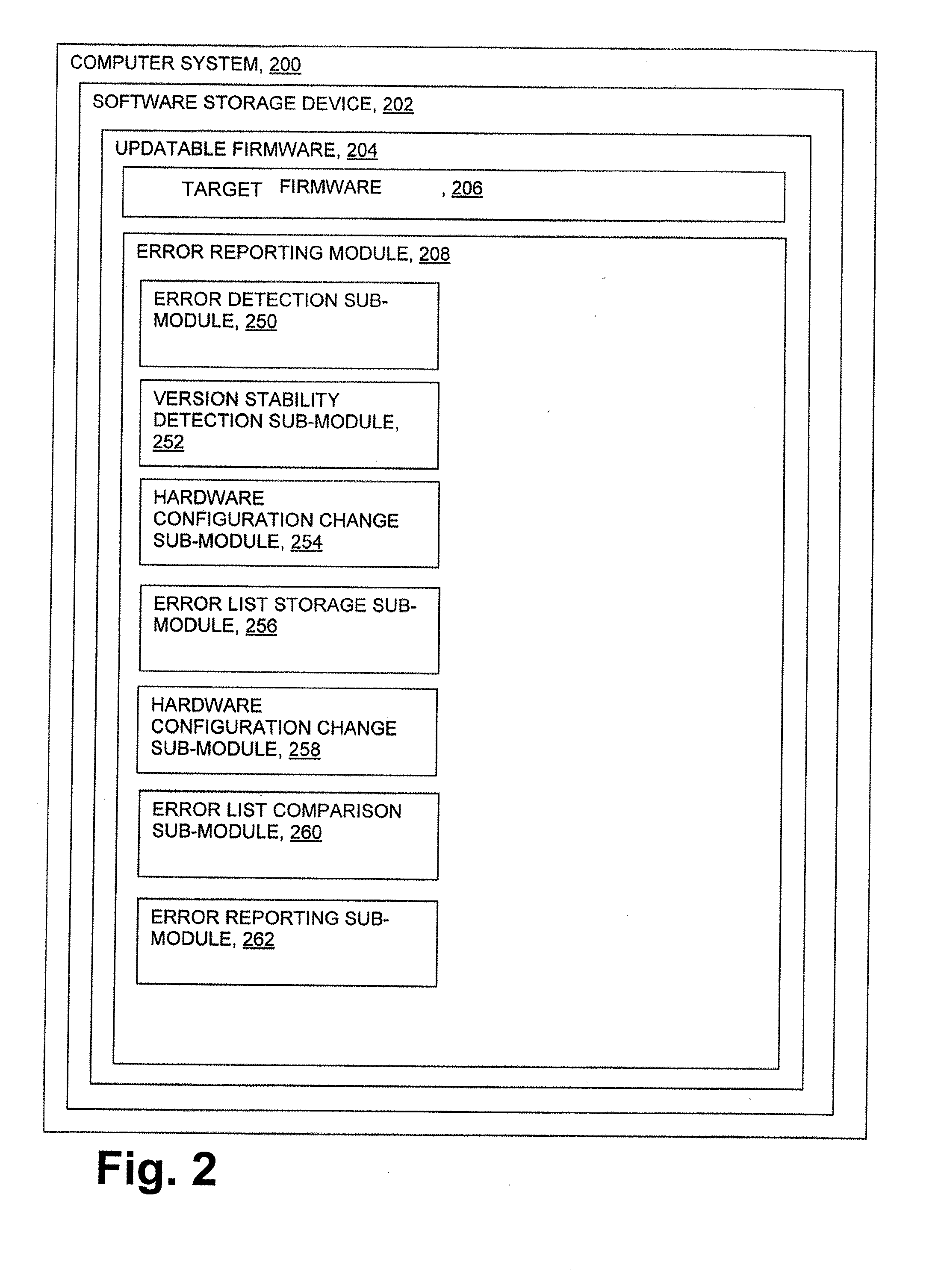
[0022]FIG. 1 shows a method 100 according to the present invention in flowchart form. The method embodiment 100 applies to a firmware update. To explain the method in general terms, initial data for firmware version N is used for a period until the version N firmware is deemed stable, collecting and updating error data all the while. (See steps S102, S104, S107 and S106.) When version N is running stably, then a full data set for firmware version N is created, stored and marked “active” based on known firmware issues associated with a known set of hardware at step S108. As system firmware updates to version N+1 (see step S110), the data set N (the first list) is transitioned to data set N+1 (the second list) after a trial period. The trial period may be based on time and / or on discrete events that occur in the computer system. For example, the trial period may be determined by the original hardware monitoring software and the new monitor per error. In this example, the trial period ...


PUM


Abstract

Error reporting software-based method where an error list for a currently-running version of some target software (or firmware) is compared to an error list for a previous versions. Helpful information can be gleaned from the comparison of error lists. For example, if it is known that the hardware configuration has not changed, as between the two lists, and there is an error on the current list that does not appear on the previous list, then this indicates that the error is in the software update and is not a hardware problem.

Description

BACKGROUND[0001]1. Field of the Invention[0002]The present invention relates to updating of software and / or firmware (herein called “non-hard-ware”) and more particularly to detection and / or identification of errors during updating of non-hard-ware.[0003]2. Description of the Related Art[0004]Methods of updating non-hardware are known. More specifically, it is known that software or firmware or both may be updated, even as the underlying hardware remains constant. These updates may be done for various reasons, such as to increase compatibility with various hardware sets, so improve performance of the non-hard-ware, to add functionality of the non-hardware, to help prevent attacks on the non-hard-ware by malicious code, to fix bugs in the non-hard-ware and so on.[0005]When non-hard-ware is run in its initial version, or is run after an update, it is known to create a list of active problems and to identify each active problem as a suspected hardware problem, a suspected software prob...

Claims


Application Information

Patent Timeline
IPC IPC(8): G06F11/36
CPCG06F11/368
Inventor FRANKE, JEFFREY MICHAELDANG, TU TOELLES, MICHAEL C.VIGNOLA, JAMES A.
Owner IBM CORP
Learn More