
Embedded Motion Sensing Technology for Integration within Commercial Ultrasound Probes

Active Publication Date: 2012-09-20
RGT UNIV OF CALIFORNIA
View PDF14 Cites 64 Cited by
  • Summary
  • Abstract
  • Description
  • Claims
  • Application Information

AI Technical Summary

Benefits of technology

[0010]Accordingly, the present invention can be described generally as an ultrasound system that includes an ultrasound machine and an ultrasound probe. The ultrasound machine displays an ultrasound image, and the ultrasound probe communicate

Problems solved by technology

Maintaining this strict orientation takes on added significance when performing image-guided interventions (e.g., needle insertion), which may result in catastrophic implications if not performed correctly.
For instance, a common pitfall, especially for novice users, is to inadvertently reverse the indicator default setting and erroneously orient the transducer as they are performing an incorrectly oriented, image-guided medical intervention.
However, these simulators are currently only available as dedicated workstations or software packages for personal computers (PCs) and require an ad hoc external handheld motion sensing peripheral device for control.
As a result, it is not possible to currently integrate the benefits of ultrasound training simulators within a real ultrasound device.

Method used


Image

  • Embedded Motion Sensing Technology for Integration within Commercial Ultrasound Probes
  • Embedded Motion Sensing Technology for Integration within Commercial Ultrasound Probes
  • Embedded Motion Sensing Technology for Integration within Commercial Ultrasound Probes

Examples


Embodiment Construction

[0016]The detailed description set forth below in connection with the appended drawings is intended as a description of presently-preferred embodiments of the invention and is not intended to represent the only forms in which the present invention may be constructed or utilized. The description sets forth the functions and the sequence of steps for constructing and operating the invention in connection with the illustrated embodiments. However, it is to be understood that the same or equivalent functions and sequences may be accomplished by different embodiments that are also intended to be encompassed within the spirit and scope of the invention.

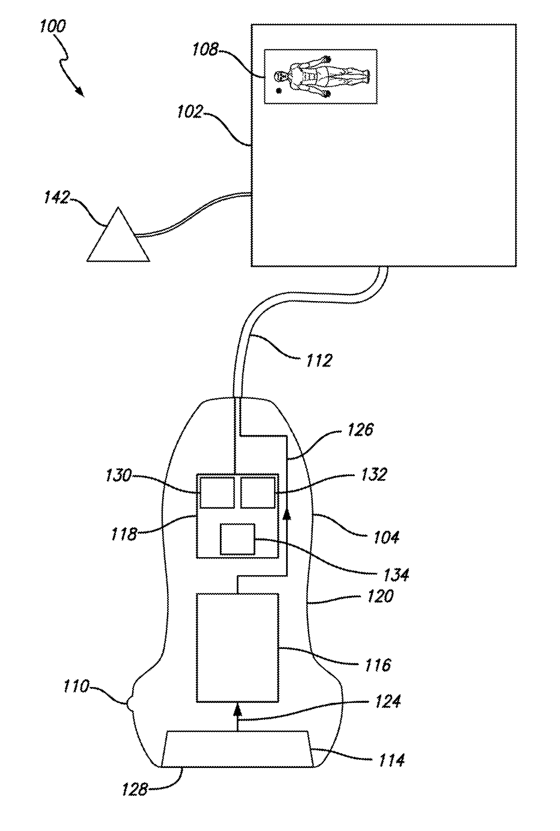
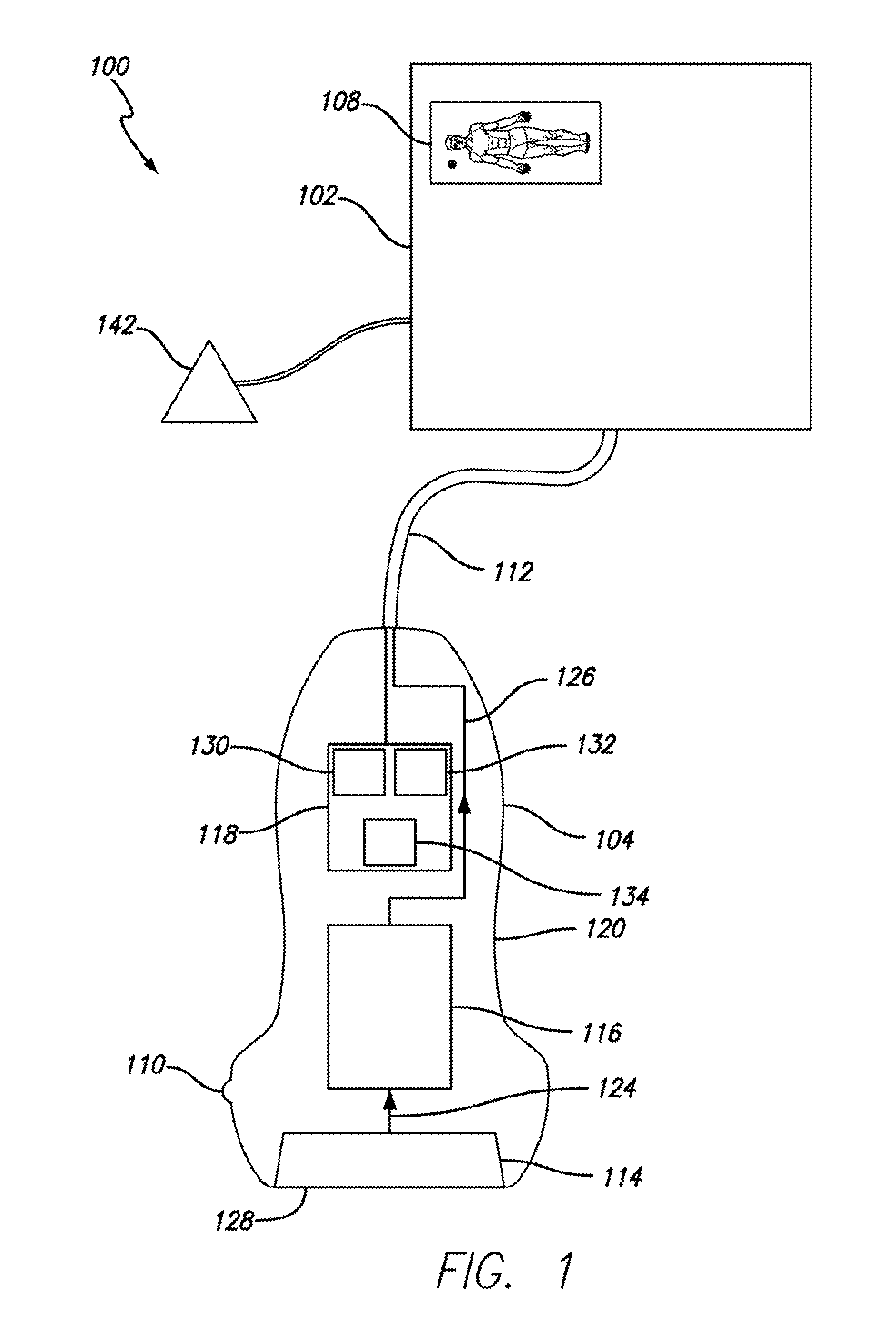
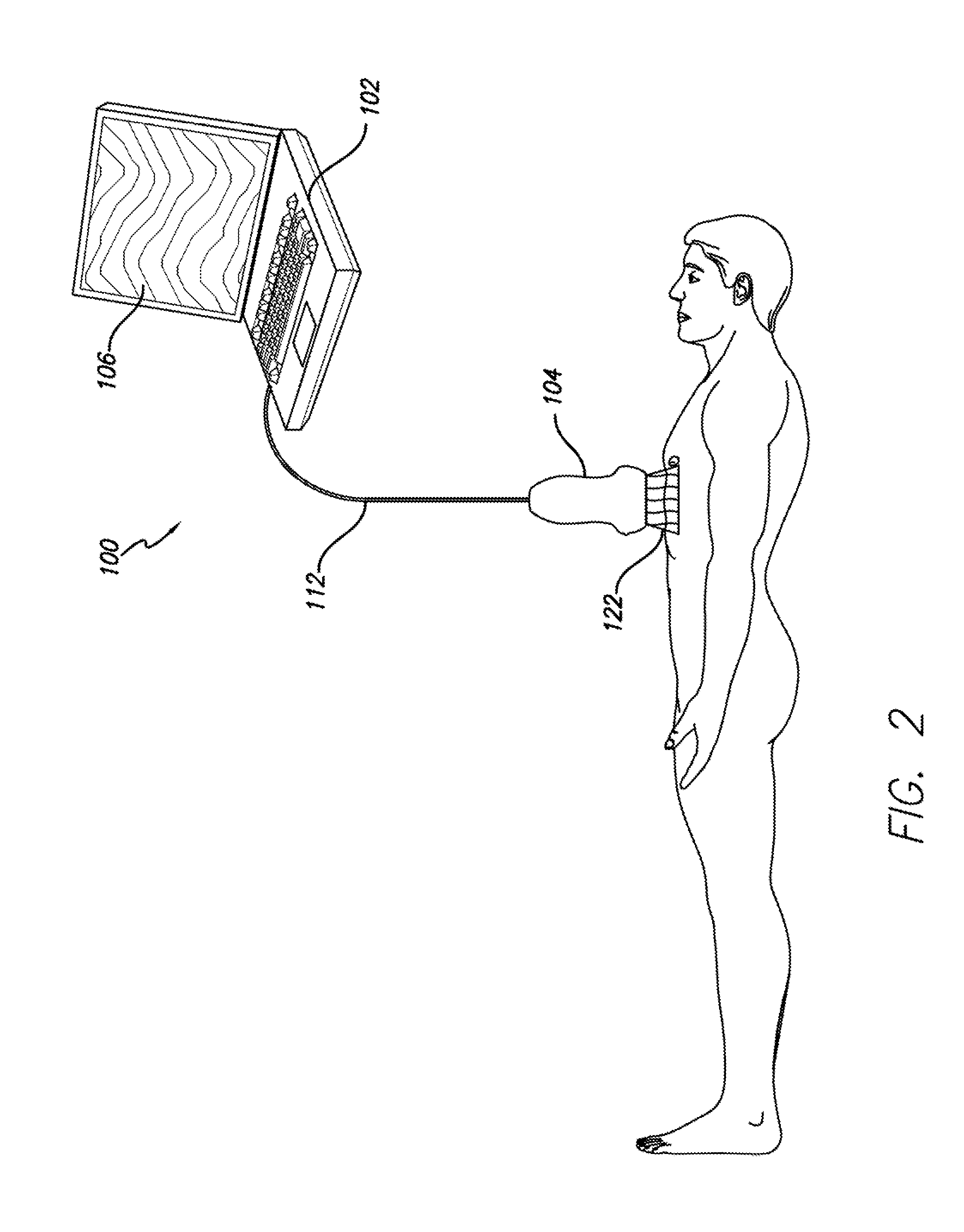
[0017]The ultrasound system 100 includes an ultrasound machine 102 and an ultrasound probe 104. The ultrasound machine 102 displays an ultrasound image 106. In a version of the invention, the image displayed by the ultrasound machine 102 includes a probe indicator icon 108. In another embodiment, the ultrasound probe 104 also includes a ref...


PUM


Abstract

An ultrasound system including an ultrasound machine and an ultrasound probe. The ultrasound probe includes an ultrasound transducer, ultrasound circuitry, a six degree of freedom (6-DOF) sensor, and a probe housing. The probe housing encases the ultrasound transducer and the 6-DOF sensor. By embedding motion-sensing technology directly within the housing of the ultrasound transducer, the position and orientation of the ultrasound probe can be tracked in an automated manner in relation to an indicator mark on the ultrasound screen. This allows assisting technologies to mitigate human error that arises from misalignment of the transducer indicator.

Description

CROSS-REFERENCES TO RELATED APPLICATIONS[0001]This patent application is a continuation-in-part and claims the benefit of U.S. patent application Ser. No. 13 / 243,758 filed Sep. 23, 2011 for Multimodal Ultrasound Training System, which is a continuation of U.S. patent application Ser. No. 11 / 720,515 filed May 30, 2007 for Multimodal Medical Procedure Training System, which is the national stage entry of PCT / US05 / 43155, entitled “Multimodal Medical Procedure Training System” and filed Nov. 30, 2005, which claims priority to U.S. Provisional Patent Application No. 60 / 631,488, entitled Multimodal Emergency Medical Procedural Training Platform and filed Nov. 30, 2004. Each of those applications is incorporated here by this reference.[0002]This patent application also claims the benefit of U.S. Provisional Application Ser. No. 61 / 491,126 filed May 27, 2011 for Data Acquisition, Reconstruction, and Simulation; U.S. Provisional Application Ser. No. 61 / 491,131 filed May 27, 2011 for Data Val...

Claims


Application Information

Patent Timeline
IPC IPC(8): A61B8/14
CPCG09B23/286A61B8/4254
Inventor SAVITSKY, ERICKATZ, DANNATANELI, GABRIELE
Owner RGT UNIV OF CALIFORNIA
Learn More