
Protective cover, camera module, and electronic device employing the same

a technology of protective cover and electronic device, applied in the field of protective cover, can solve problems such as reducing the operating life of the camera lens

Inactive Publication Date: 2012-09-13
FIH (HONG KONG) LTD
View PDF9 Cites 26 Cited by
  • Summary
  • Abstract
  • Description
  • Claims
  • Application Information

AI Technical Summary

Problems solved by technology

However, the flash bulb 242 may emit hard light because the camera lens 222 and the flash bulb 242 are located close to each other, causing overexposure of the camera lens 222, which may decrease the operating life of the camera lens 222.

Method used


Image

  • Protective cover, camera module, and electronic device employing the same
  • Protective cover, camera module, and electronic device employing the same
  • Protective cover, camera module, and electronic device employing the same

Examples


Embodiment Construction

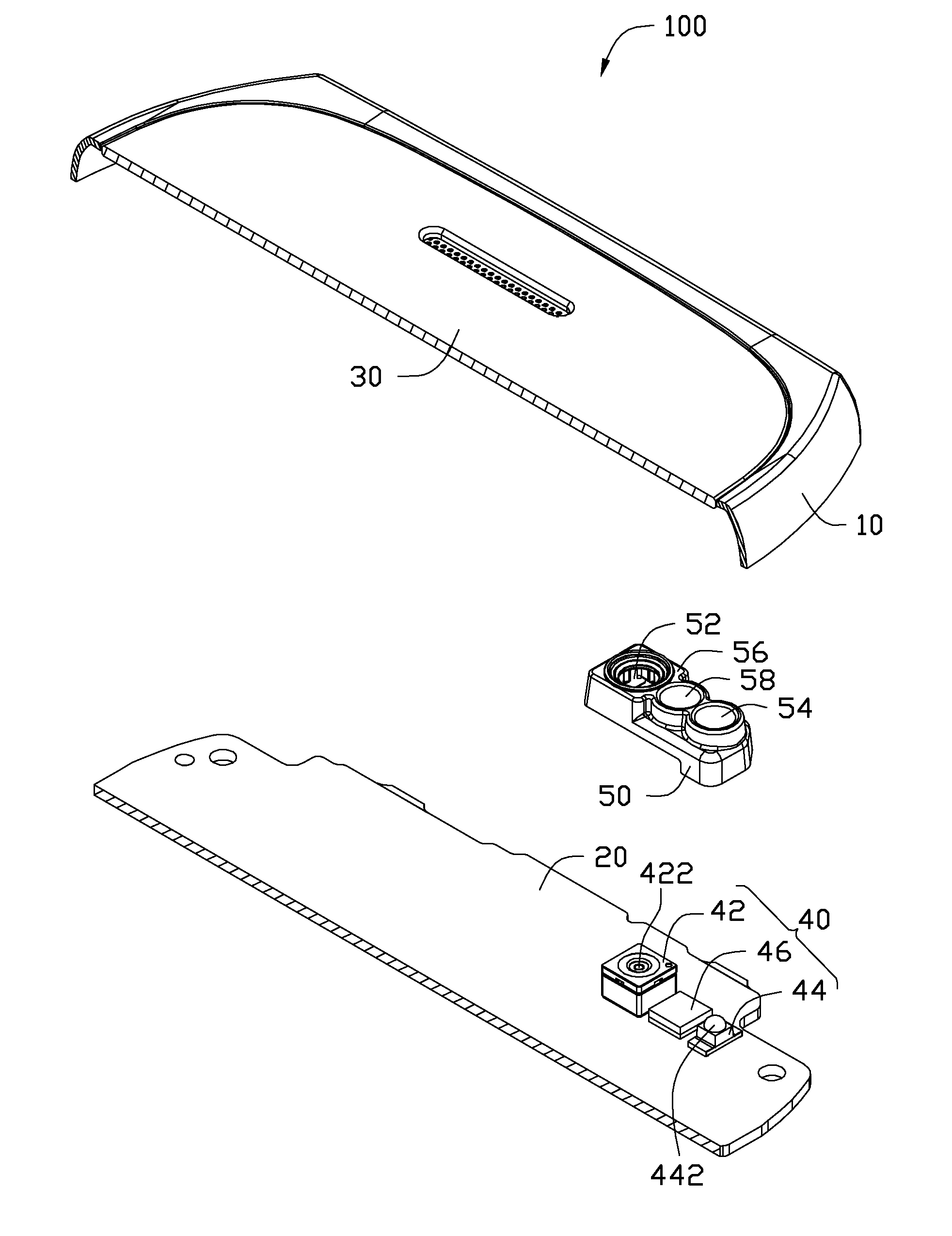
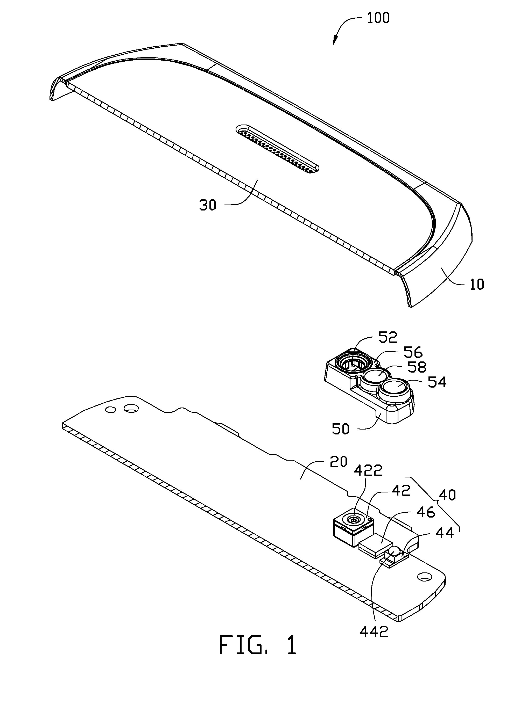
[0015]FIG. 1 shows an exploded view of one embodiment of an electronic device 100 including a protective over 50. The electronic device 100 can be a mobile phone or a personal digital assistant. The mobile phone is taken here as an example to illustrate the disclosure.

[0016]The electronic device 100 further includes a housing 10, a circuit board 20, a window plate 30, and a camera module 40. In one embodiment, the housing 10 can be a partial cover of the electronic device 100. The circuit board 20 can be a motherboard of the electronic device 100 and is received within the housing 10. The circuit board 20 is capable of holding many electronic components of the electronic device 100, while providing supports and connections for the electronic components.

[0017]The camera module 40 includes a camera unit 42, a flash device 44, and a light intensity sensor 46. The camera unit 42 is located on and is electrically connected to the circuit board 20, and is capable of recording and storing ...


PUM


Abstract

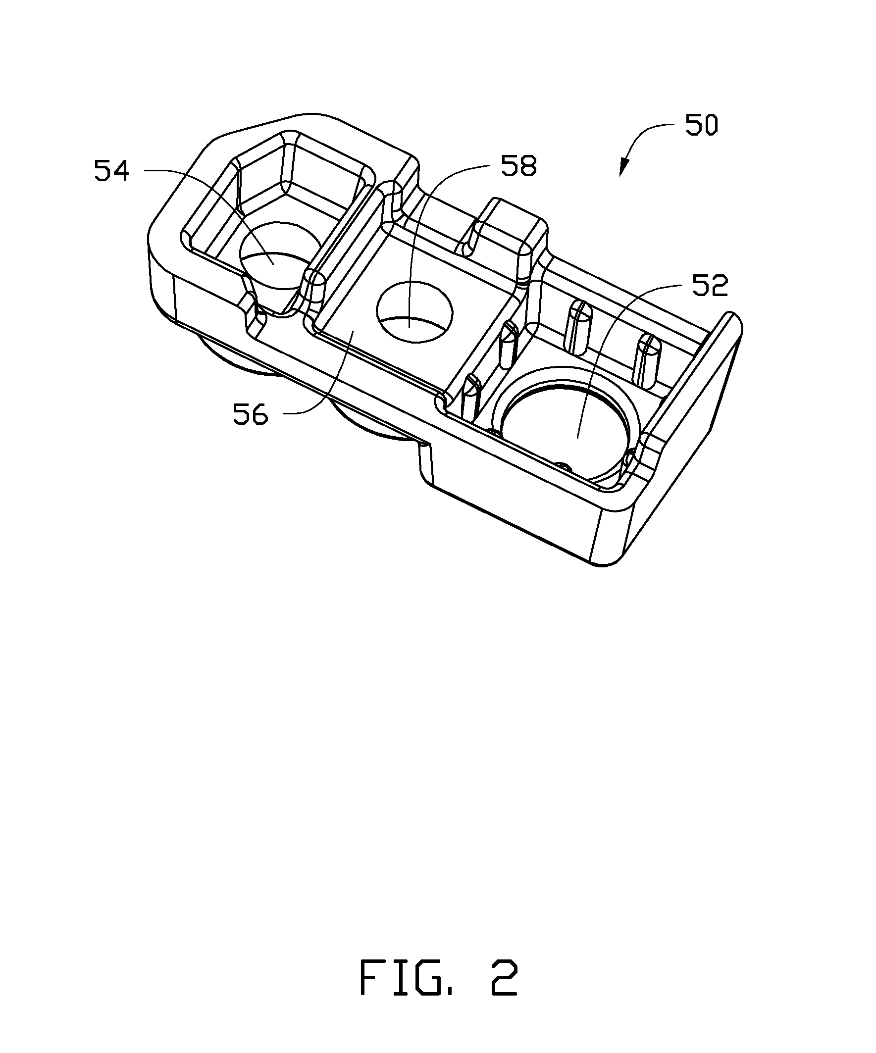
An electronic device includes a housing, a circuit board, and a camera module. The camera module includes a camera unit, a flash device, and a protective cover. The camera unit records and stores images, and the protective cover protects the camera unit and the flash device. The protective cover includes an opening, a light hole, and a separation portion located between the opening and the light hole. The light from the flash device is diffused and passes through the light hole. The camera unit and the flash device are separated by the separation portion to prevent the light of the flash device from entering camera unit through the opening.

Description

[0001]BACKGROUND[0002]1. Technical Field[0003]The disclosure generally relates to cover structures, and more particularly to a protective cover, and a camera module and an electronic device employing the same.[0004]2. Description of the Related Art[0005]Built-in camera modules are widely used in different electronic devices, such as mobile phones. To get a better result, corresponding flash modules are used in the electronic devices to match the camera modules.[0006]Referring to FIG. 6, a conventional camera module 200 generally includes a camera 220 and a flash unit 240, which are adjacently located on and is electrically connected to a motherboard 300. The camera 220 includes a camera lens 222, and the flash unit 240 includes a flash bulb 242 used as an auxiliary light source to increase light for the camera lens 222. However, the flash bulb 242 may emit hard light because the camera lens 222 and the flash bulb 242 are located close to each other, causing overexposure of the camer...

Claims


Application Information

Patent Timeline
Patent Type & Authority Applications(United States)
IPC IPC(8): H04N5/225G03B15/05G03B11/04G03B30/00
CPCG03B11/043H04M1/0264
Inventor HSIUNG, MING-CHUN
Owner FIH (HONG KONG) LTD
Learn More