
Chuck mechanism for dental handpiece and dental handpiece using the mechanism

a technology of dental handpieces and chucks, applied in dental surgery, medical science, dentistry, etc., can solve the problems of inconvenient device use, inability to adequately exert elastic function of lock members, and bulky head parts, etc., and achieve the effect of reducing axial runout (deflection of axial center)

Active Publication Date: 2012-07-26
MORITA MFG CO LTD
View PDF5 Cites 8 Cited by
  • Summary
  • Abstract
  • Description
  • Claims
  • Application Information

AI Technical Summary

Benefits of technology

The present invention provides a chuck mechanism for a dental handpiece that can adequately exert elastic chuck function and reduce axial runout of the rotor and the rotary tool. The chuck mechanism includes an annular chucking member with an elastic chucking piece having a chucking pawl for elastically engaging with a locking groove in the rotary tool. The elastic chucking piece can be deformed against elastic force to disengage from the locking groove and allow for easy removal of the rotary tool. The dental handpiece also includes a tubular rotor outer member that can be fitted to the chucking member and a working body that can be fitted in a non-disengageable manner to further reduce abrasion and solidification of powder between the rotor and the rotary tool.

Problems solved by technology

In the embodiment, it is pointed out as a problem that elastic function of the lock member cannot be adequately exerted even when the lock member is designed to be able to elastically ream (enlarge) in a limited space.
The chuck device disclosed in PTL 1 as a new invention adequately exerts elastic function of the lock member; however, the head part becomes bulky in the axial center direction of the bar tube because the chuck device is positioned on the upper part of the upper bearing, so that such a device may not be suitable for a dental handpiece which is used to be inserted into narrow oral cavity.

Method used


Image

  • Chuck mechanism for dental handpiece and dental handpiece using the mechanism
  • Chuck mechanism for dental handpiece and dental handpiece using the mechanism
  • Chuck mechanism for dental handpiece and dental handpiece using the mechanism

Examples


Embodiment Construction

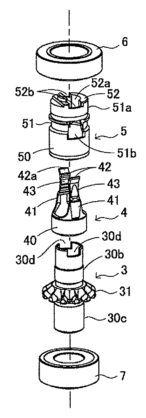
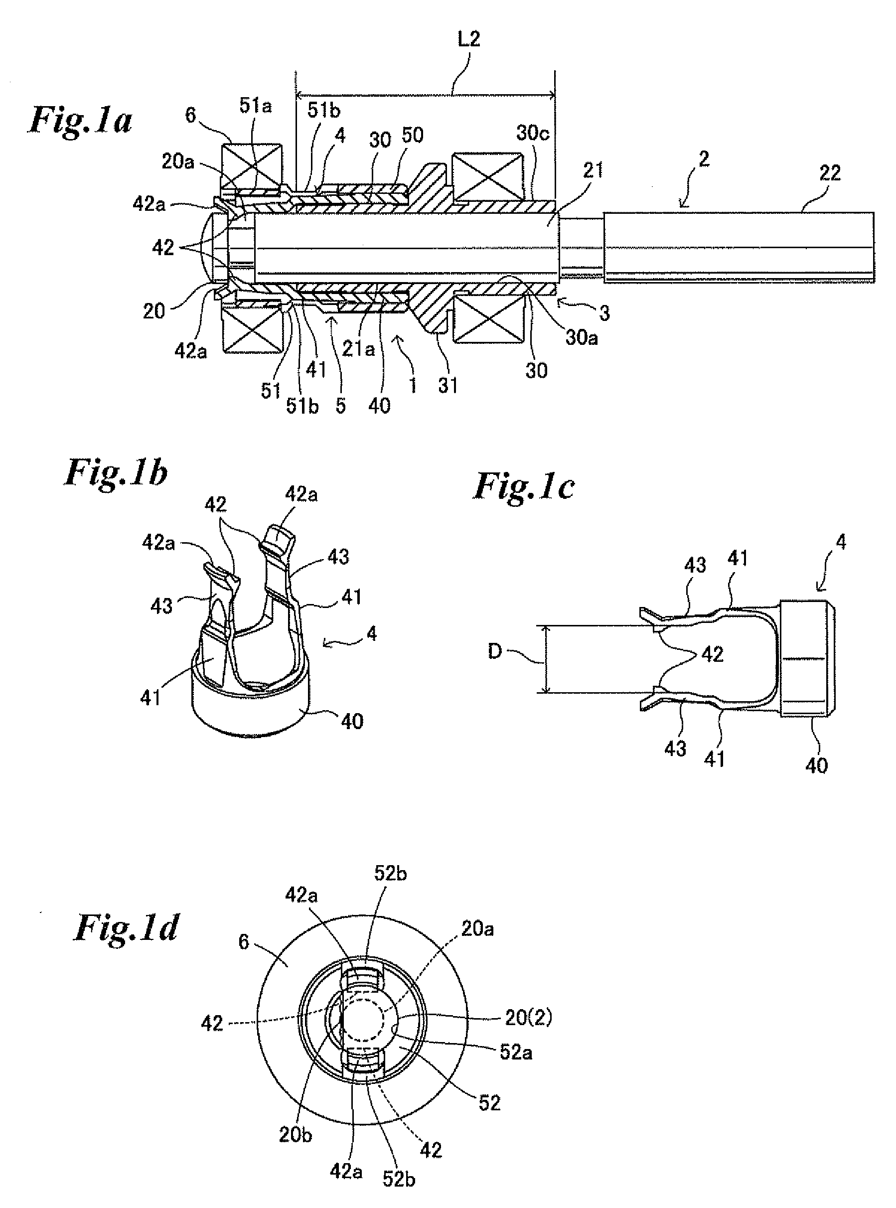
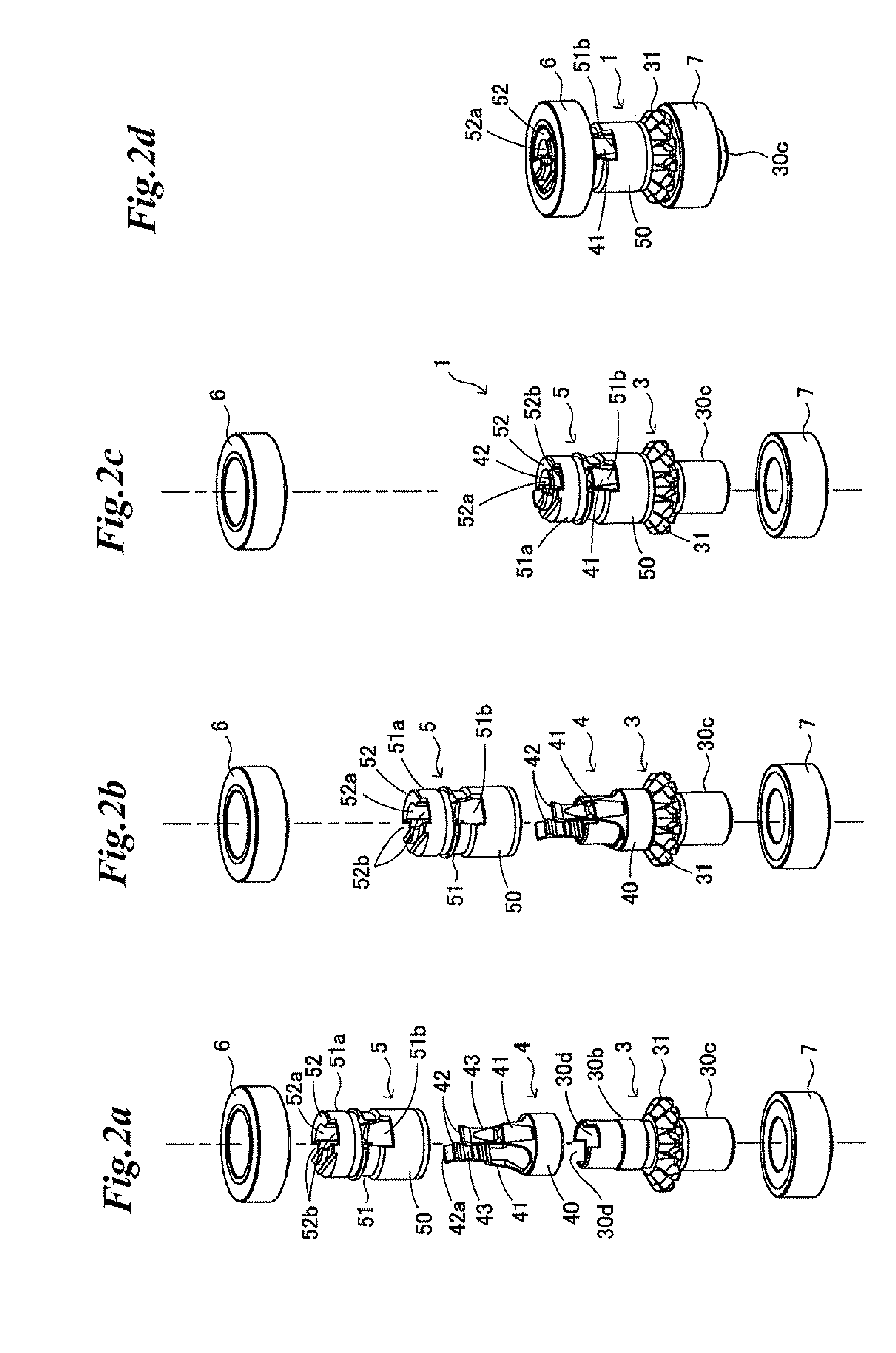
[0039]The embodiments of a chuck mechanism for a dental handpiece and a dental handpiece using the mechanism according to the present invention are explained based on the drawings. In the chuck mechanism 1 shown in FIG. 1a, a tubular rotor 3 is externally fitted to a shank part 21 of a rotary tool (a contra-bar or a latch bar) 2. The rotor 3 has a tool guide tube part 30 to which the shank part 21 of the rotary tool 2 is inserted so as to be held along the entire length and an inner circumference 30a of the tool guide tube part 30 circumscribes with the shank part 21 of the rotary tool 2. The circumscribed length is represented as L2. The chuck mechanism 1 has a chucking member 4 as shown in FIG. 1b and FIG. 1c. The chucking member 4 has a cylindrical base part 40 which is externally fitted to and integrated with an outer circumference 30b of the tool guide tube part 30 on the side of a base end part 20 of the rotary tool 2 (called outer circumference on the base end side, hereinaft...


PUM


Abstract

A chuck mechanism for a dental handpiece and a dental handpiece with the chuck mechanism are disclosed. The chuck mechanism holds the columnar rotary tool for dental care rotatably with an annular rotor of the dental handpiece and the columnar rotor tool is concentrically detachable to the annular rotor which is rotatably attached to a head part of the dental handpiece. The chuck mechanism is characterized by an annular chucking member which comprises a cylindrical base part into which the annular rotor is integrally fitted and an elastic chucking piece having a chucking pawl for engaging with a locking groove formed at a base end of the rotary tool. The chuck mechanism enables the rotary tool to be easily removed from the annular rotor by elastically deforming the elastic chucking piece against elastic force of the elastic chucking piece to disengage the chucking pawl from the locking groove.

Description

BACKGROUND OF THE INVENTION[0001]1. Technical Field[0002]The present invention relates to a chuck mechanism for detachably holding a rotary tool at a head part of a dental handpiece, specifically a micro-motor hand-held piece and further to a dental handpiece using the chuck mechanism.[0003]2. Background Art[0004]A dental micro-motor hand-held piece is designed such that a columnar rotary tool for cutting teeth (called contra-bar or latch bar) is detachably attached on a head part and axially rotates by rotary drive force of a micro-motor (rotary drive portion) embedded in the hand-held piece body. Several kinds of rotary tools are prepared and a suitable one is selected from them by an operator depending on the state of affected region and is used by attaching it on the head part. When the tip part (cutting operation part) of the rotary tool becomes worn, the tool is exchanged to a new one. Therefore, the rotary tool is designed so as to be easily attached or detached by a chuck me...

Claims


Application Information

Patent Timeline
Patent Type & Authority Applications(United States)
IPC IPC(8): A61C1/14
CPCA61C1/142A61C1/141A61C1/144
Inventor TANAKA, HITOSHIONO, HIROYUKINAKAYAMA, SHOZO
Owner MORITA MFG CO LTD
Learn More