
Quick corrector for a time related magnitude indicator for a timepiece

a technology of magnitude indicator and quick corrector, which is applied in the direction of normal winding, instruments, and horology, etc., can solve the problems of large number of levers, large number of efficient devices, and large component siz

Active Publication Date: 2012-07-19
OMEGA SA
View PDF8 Cites 28 Cited by
  • Summary
  • Abstract
  • Description
  • Claims
  • Application Information

AI Technical Summary

Benefits of technology

[0039]Second control means for a second function, distinct from said first function, connected to second display means and capable of changing, under the effect of an action by a user, from a let down rest position to a control position for the instantaneous release of said second function, wherein at the end of said instantaneous release, said second control means is returned to said let down rest position by return means.

Problems solved by technology

However, the drawback of these simple devices is that there is a risk of a sealing defect at the location of the push button used for correcting the display.
However, this efficient device requires a large number of levers, and occupies space in an area which is already very overcrowded.
This ingenious device requires components of very small size, which are difficult to assemble and the device is quite fragile, in particular in the event of shocks.
This construction offers an interesting alternative to known correction control means, but it requires special construction for the timepiece concerned, particular care as regards sealing, and involves high fabrication costs.
Other than correction mechanisms based on the use of the winding and time-setting stem, there exist few solutions for performing these corrections, except through the use of additional push buttons, which each time raise sealing problems and involve significant expense.

Method used


Image

  • Quick corrector for a time related magnitude indicator for a timepiece
  • Quick corrector for a time related magnitude indicator for a timepiece
  • Quick corrector for a time related magnitude indicator for a timepiece

Examples


Embodiment Construction

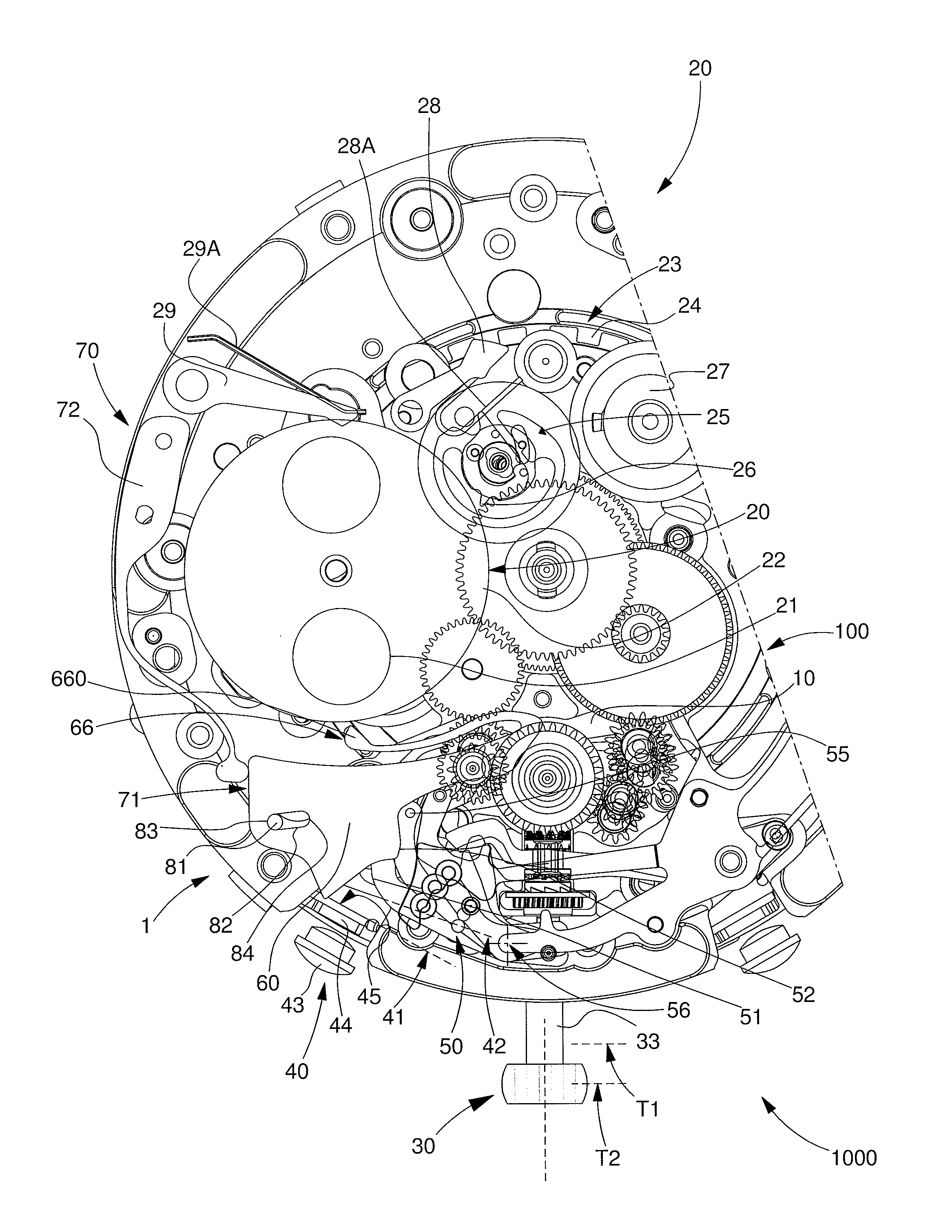
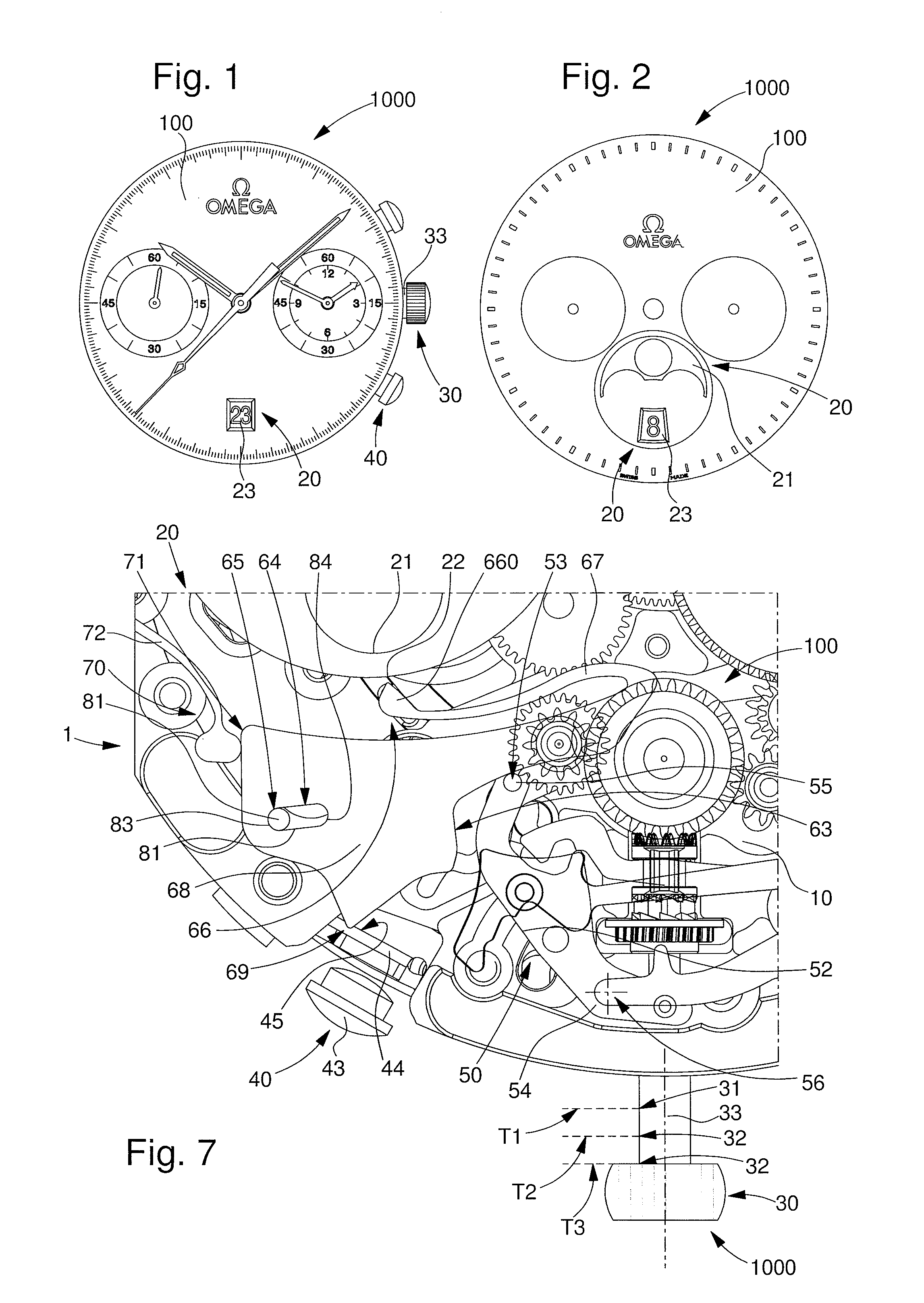
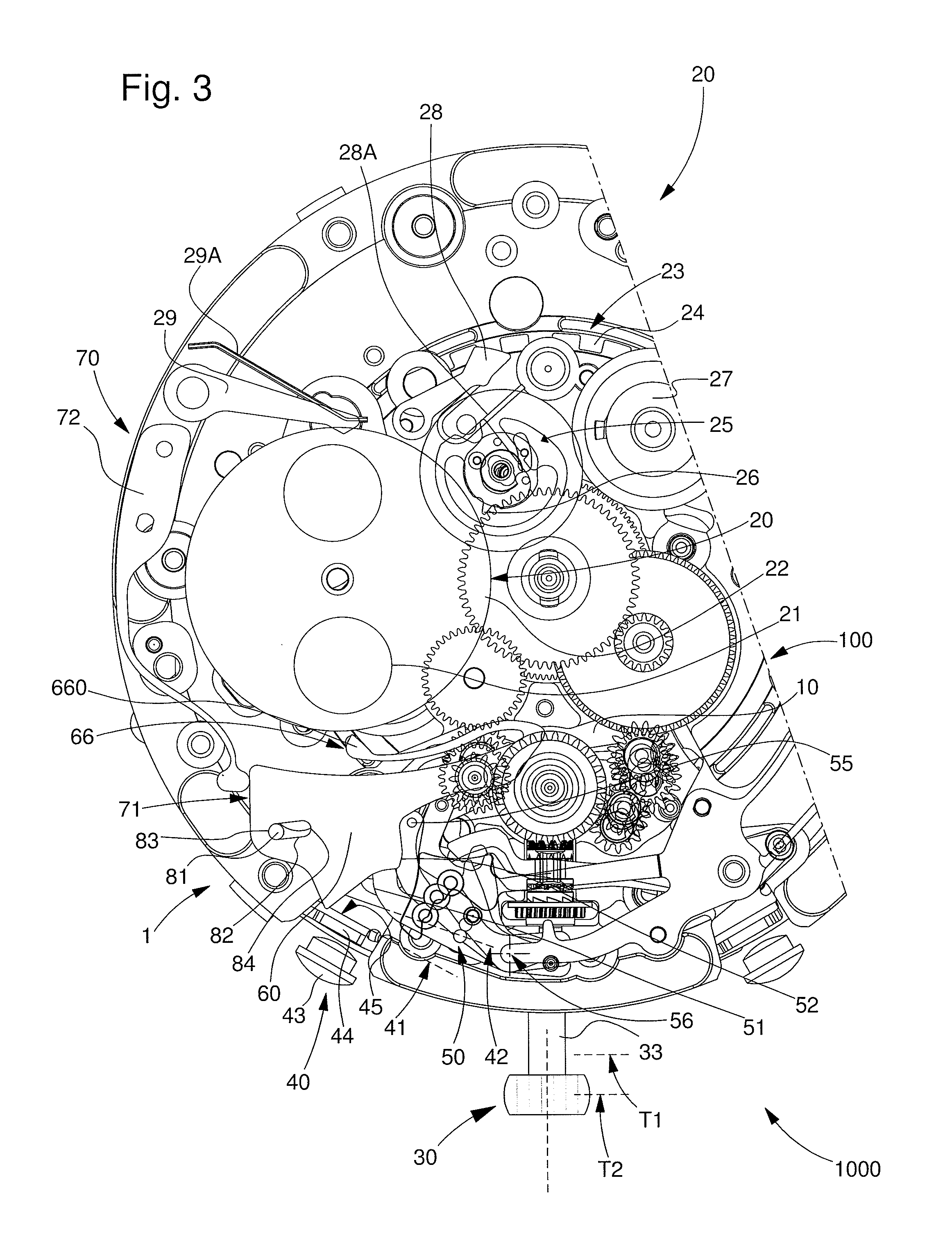
[0052]The invention concerns the field of horology, and more specifically the field of timepiece including complications for the display of time related magnitudes, such as the date, moon phase, day, month or suchlike, or for the display of physical magnitudes, such as atmospheric pressure or other.

[0053]More specifically, the invention is described in the application to the field of chronographs fitted with these complications.

[0054]Thus, the invention concerns a quick correction mechanism 1 for a function display indicator 20 for a movement 100 or a timepiece 1000.

[0055]This movement 100 or this timepiece 1000 conventionally includes, directly or indirectly mounted on a plate 10:[0056]First control means 30 for at least a first function, which is connected to first display means and is capable of occupying a let down position 31 or at least one wound control position 32. This first function may, in particular, consist in setting the time of the timepiece, or in winding the timepie...


PUM


Abstract

A corrector (1) for a function indicator (20) for a movement (100) including: a first control mechanism (30) for a first function, in a let down (31) or wound (32) position, a second control mechanism (40) for a second function, in a let down position (41) or release control position (42) followed by a return to the preceding position, and a display indicator (20) for a third function. First mobile part (50) driven by the first control mechanism (30) occupies a letting down (51) / winding (52) position, when the mechanism occupies the let down (31) / wound (32) position. Second mobile part (60) actuating the indicator (20) is driven by the second control mechanism (40) changing into the control position (42) when the first mobile part (50) is in a winding position (52) and cooperates with this latter in the letting down position (51), under the action of return mechanism (70).

Description

[0001]This application claims priority from European Patent Application No. 10191387.9 filed Nov. 16, 2010, the entire disclosure of which is incorporated herein by reference.Field of the invention[0002]The invention concerns a quick corrector mechanism for a function display indicator for a movement or a timepiece, wherein said movement or said timepiece includes, directly or indirectly mounted on a plate:[0003]First control means for at least a first function, connected to first display means and capable of occupying a let down position or at least one wound control position.[0004]Second control means for a second function, distinct from said first function, connected to second display means and capable of changing, under the effect of an action by a user, from a let down rest position to a wound control position for the instantaneous release of said second function, wherein at the end of said instantaneous release, said second control means is returned to said let down rest posit...

Claims


Application Information

Patent Timeline
Patent Type & Authority Applications(United States)
IPC IPC(8): G04B27/04G04B19/24G04B19/26
CPCG04B27/026G04F7/0804G04F7/0871G04F7/0866G04F7/0842
Inventor FARRON, ADRIENRUFENACHT, CHRISTIAN
Owner OMEGA SA
Learn More