Holding Device for a Displaceable Sensor

Inactive Publication Date: 2012-07-19
EADS DEUT GMBH
View PDF1 Cites 5 Cited by
  • Summary
  • Abstract
  • Description
  • Claims
  • Application Information

AI Technical Summary

Benefits of technology

[0007]Exemplary embodiments of the present invention are directed to a holding device for a displaceable sensor, which can be used inside an aircraft nose and can be oriented to a target, and which can be fit to a support structure. Because the holding device has a compact construction, it possible to rapidly orient the sensor to the target and also allow the sensor to be rapidly repositioned in the case of a moving target and / or a moving support structure.

Problems solved by technology

However, as a result of the arrangement of the axes of rotation with respect to one another, repositioning of the sensor with respect to a target results in a wobbling movement of the sensor, which makes it not very suitable for use in aviation.
The sensor center of gravity thus moved on a spherical surface, which likewise makes the arrangement not very suitable for use in aviation.

Method used


Image

  • Holding Device for a Displaceable Sensor
  • Holding Device for a Displaceable Sensor
  • Holding Device for a Displaceable Sensor

Examples


Embodiment Construction

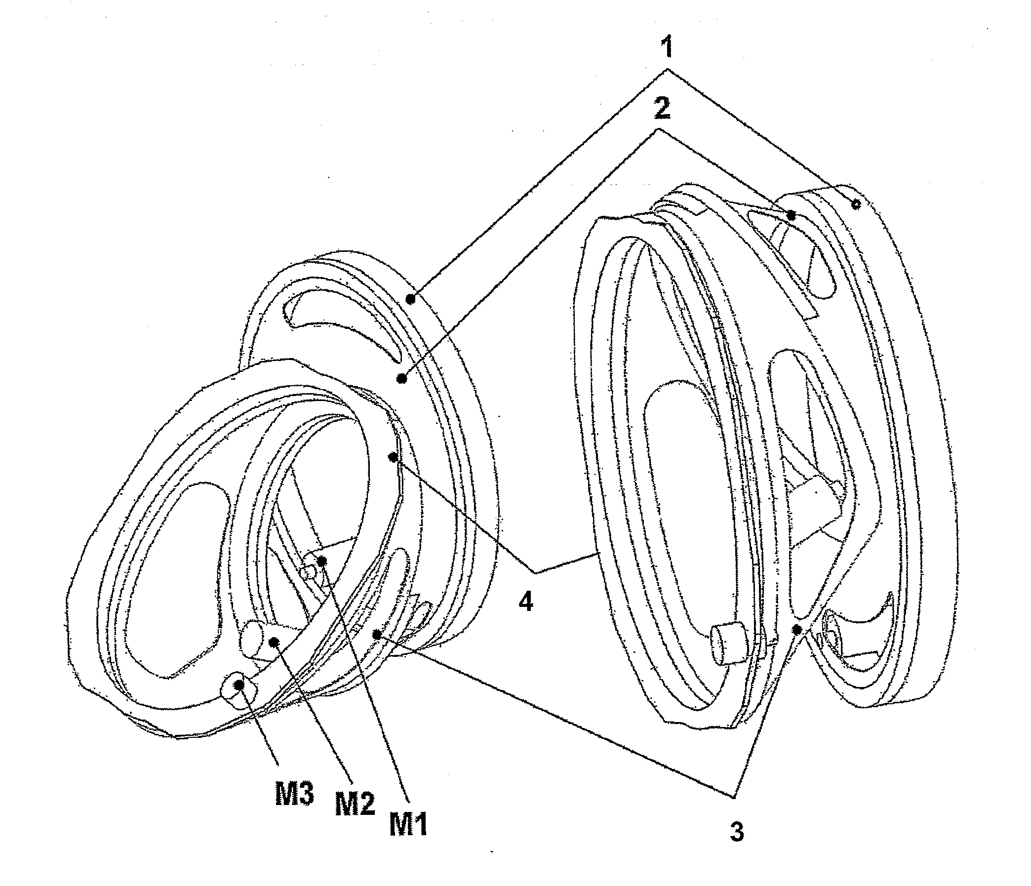
[0020]For the orientation of a sensor or an antenna, two or three motor-driven rings are required according to the invention in order to always orient the sensor perpendicular to a target point within a particular angle spectrum.

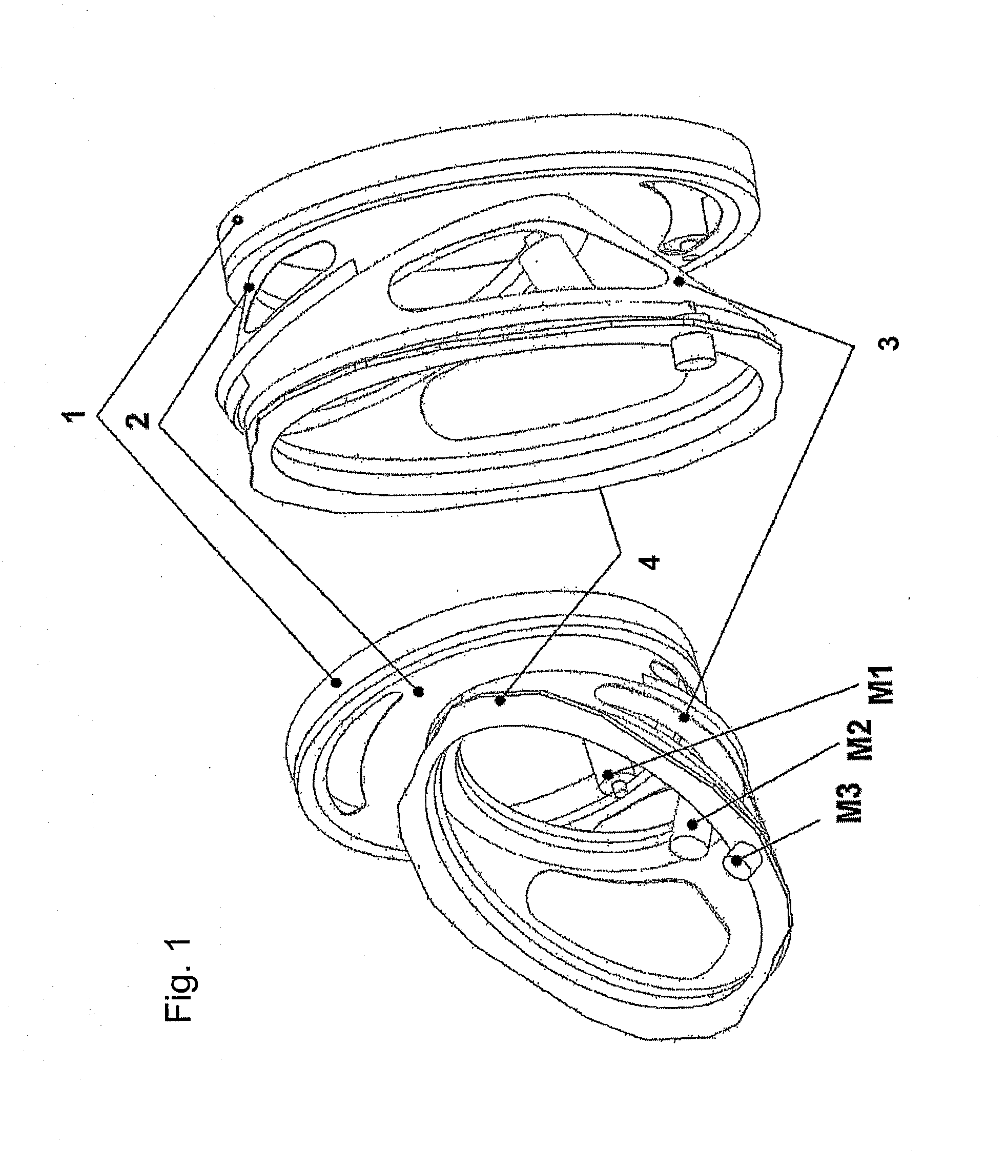
[0021]FIG. 1 shows a holding device having a first rotatably mounted ring 2, a second rotatably mounted ring 3 and a third rotatably mounted ring 4. The first rotatably mounted ring 2 is fastened to a support structure 1 of the holding device. The second rotatably mounted ring 3 is arranged between the third rotatably mounted ring 4 and the first rotatably mounted ring 2. The sensor (not illustrated) is fastened to the third rotatably mounted ring 4. Motors M2, M3, M4 are additionally fastened to the rotatably mounted rings 2, 3, 4 in order to drive the rings 2, 3, 4.

[0022]The third rotatably mounted ring 4 is connected to the sensor and is used to compensate for rolling. This non-rotation of the antenna with respect to a particular plane could also be effec...


PUM


Abstract

A holding device for a displaceable sensor is provided. The holding device has two or three motor-rotatable rings for accommodating a sensor, and the axes of rotation of the two or three motor-rotatable rings are oblique with respect to one another. The axes of rotation intersect at a virtual pivot point.

Description

BACKGROUND AND SUMMARY OF THE INVENTION[0001]The present invention relates to a holding device for a displaceable sensor, which can be oriented to a target, on a support structure. Such sensors may be, for example, radar sensors, camera sensors or generally transmitters and / or receivers of electromagnetic radiation.[0002]The term “sensor” for an orientable functional element in the context of the present application is thus not restricted to receiving devices but may likewise include transmitting devices or combined transmitting / receiving devices for electromagnetic radiation.[0003]In order to be able to orient such sensors to a target, a displaceable holding device is required for the sensor. If the support structure itself is likewise displaceable, for example part of an aircraft, a spacecraft, a watercraft or a land vehicle, this holding device must be able to reposition the sensor in such a manner that the latter remains oriented to the target. This also applies when the target ...

Claims


Application Information

Patent Timeline
IPC IPC(8): G12B5/00
CPCF16M11/105F16M11/12H01Q3/08F16M11/2064H01Q1/125F16M11/18
Inventor CHRISTOF, HORSTSANDER, JOERGBICHLER, BARTHOLOMAEUSLOEHNER, ANDREASDITTMAR, REINERROTHMAIER, ULRICH
Owner EADS DEUT GMBH
Why Eureka
Try Eureka