Synchronization detecting method and synchronization detecting circuit
a detection method and detecting circuit technology, applied in the field of synchronization detection methods and synchronization detection circuits, can solve the problems of user data not being normally obtained, burst errors occurring beyond the correction capability of subsequent error correction circuits, etc., and achieve the effect of improving the reproducing capability of reproducing devices and high correction capability
- Summary
- Abstract
- Description
- Claims
- Application Information
AI Technical Summary
Benefits of technology
Problems solved by technology
Method used
Image

Examples
first exemplary embodiment
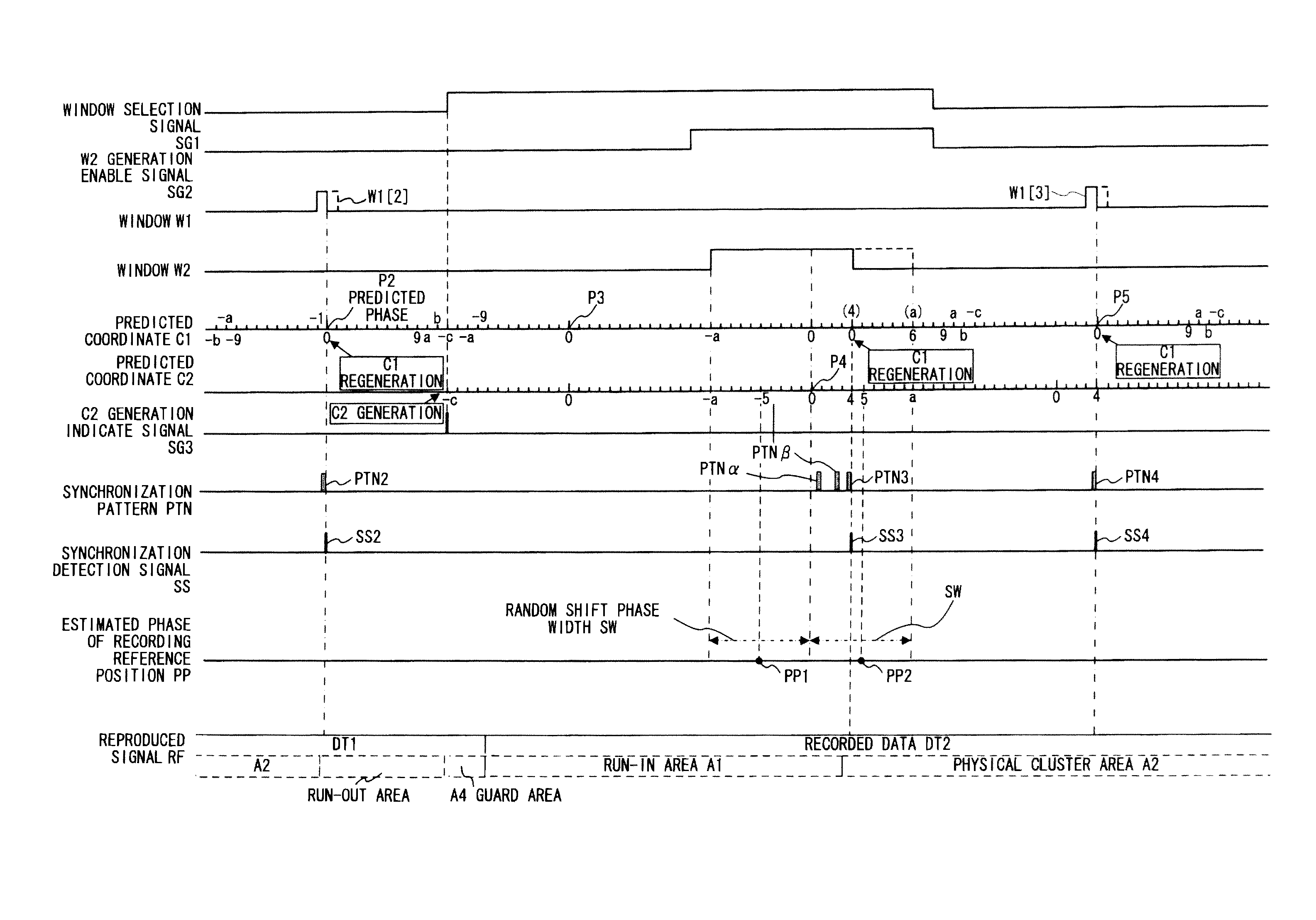
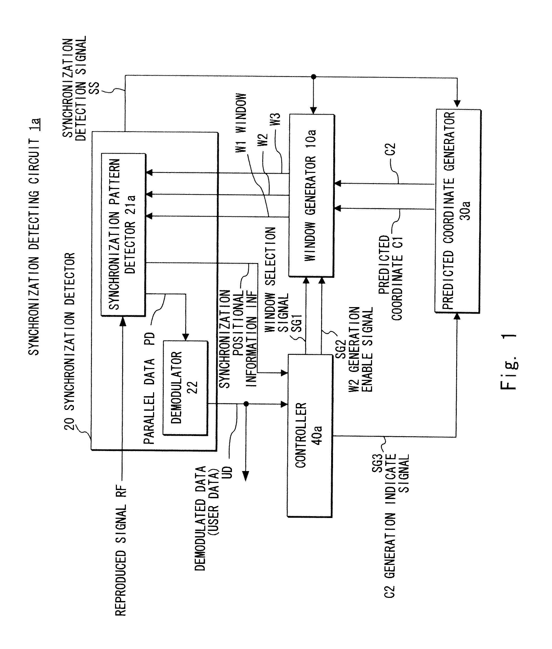
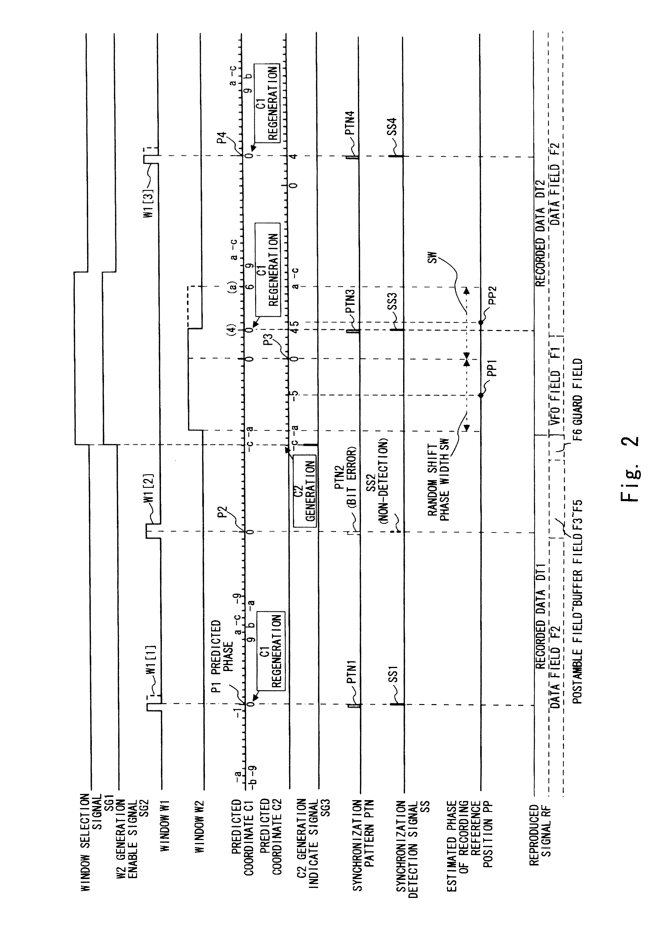
[0080]A synchronization detecting circuit 1a according to the first exemplary embodiment shown in FIG. 1 is different from the synchronization detecting circuit 1 shown in FIG. 12 in that the synchronization detecting circuit 1a includes a window generator 10a, a synchronization pattern detector 21a, a predicted coordinate generator 30a, and a controller 40a. The window generator 10a generates a window W3 in addition to the windows W1 and W2. The synchronization pattern detector 21a uses one of the windows W1 to W3 to detect the synchronization pattern that appears in the reproduced signal RF. The predicted coordinate generator 30a generates a predicted coordinate C2 which is obtained by replicating the predicted coordinate C1 and used for generating the windows W2 and W3 in addition to the predicted coordinate C1. The controller 40a generates a signal indicating the timing of generating the predicted coordinate C2 (hereinafter referred to as C2 generation indicate signal) SG3 in ad...
second exemplary embodiment
[0103]A synchronization detecting circuit 1b according to the second exemplary embodiment shown in FIG. 5 is different from the above first exemplary embodiment in that the synchronization detecting circuit 1b further includes a window adjusting part 50 in addition to the configuration of the synchronization detecting circuit 1a shown in FIG. 1. Upon detecting the synchronization pattern with the window W2, the window adjusting part 50 supplies a one-sided phase width (hereinafter referred to as window one-sided phase width) WW of the window W2 which is to be generated next to the window generator 10a to be instructed to change (narrow) the phase width of the window W2, and supplies phase offset value 0V to the predicted coordinate generator 30a to be instructed to correct the predicted coordinate C2 which is to be generated next.
[0104]In operation, assume a case where the reproduced signal RF is obtained by sequentially reproducing five recording unit blocks RUB0 to RUB4 recorded i...
third exemplary embodiment
[0124]A synchronization detecting circuit 1c according to the third exemplary embodiment shown in FIG. 7 is different from the above second exemplary embodiment in that the window adjusting part 50a supplies a signal instructing the extension of the window W2 (hereinafter referred to as extension indicate signal) SG4 to the window generator 10a in addition to the window one-sided phase width WW. The window adjusting part 50a manages, as shown in FIGS. 8A to 8D, an internal state STS that transits between a search state SRCH in which the optimization processing of the window W2 shown in the second exemplary embodiment is executed and an adjustment state ADJ in which the extension processing of the window W2 in the third exemplary embodiment is executed.
[0125]According to the synchronization detecting circuit 1c, the disturbance of the reproducing clock (not shown) generated from the former PLL circuit (not shown) or the like can be addressed. In general, the PLL circuit forces to gen...
PUM
| Property | Measurement | Unit |
|---|---|---|
| width | aaaaa | aaaaa |
| length | aaaaa | aaaaa |
| phase width | aaaaa | aaaaa |
Abstract
Description
Claims
Application Information
 - R&D
- Intellectual Property
- Life Sciences
- Materials
- Tech Scout
- Unparalleled Data Quality
- Higher Quality Content
- 60% Fewer Hallucinations
Browse by: Latest US Patents, China's latest patents, Technical Efficacy Thesaurus, Application Domain, Technology Topic, Popular Technical Reports.
© 2025 PatSnap. All rights reserved.Legal|Privacy policy|Modern Slavery Act Transparency Statement|Sitemap|About US| Contact US: help@patsnap.com