
Mono-directional Ultrasound Transducer for Borehole Imaging

Inactive Publication Date: 2012-06-28
SONDEX WIRELINE
View PDF9 Cites 5 Cited by
  • Summary
  • Abstract
  • Description
  • Claims
  • Application Information

AI Technical Summary

Benefits of technology

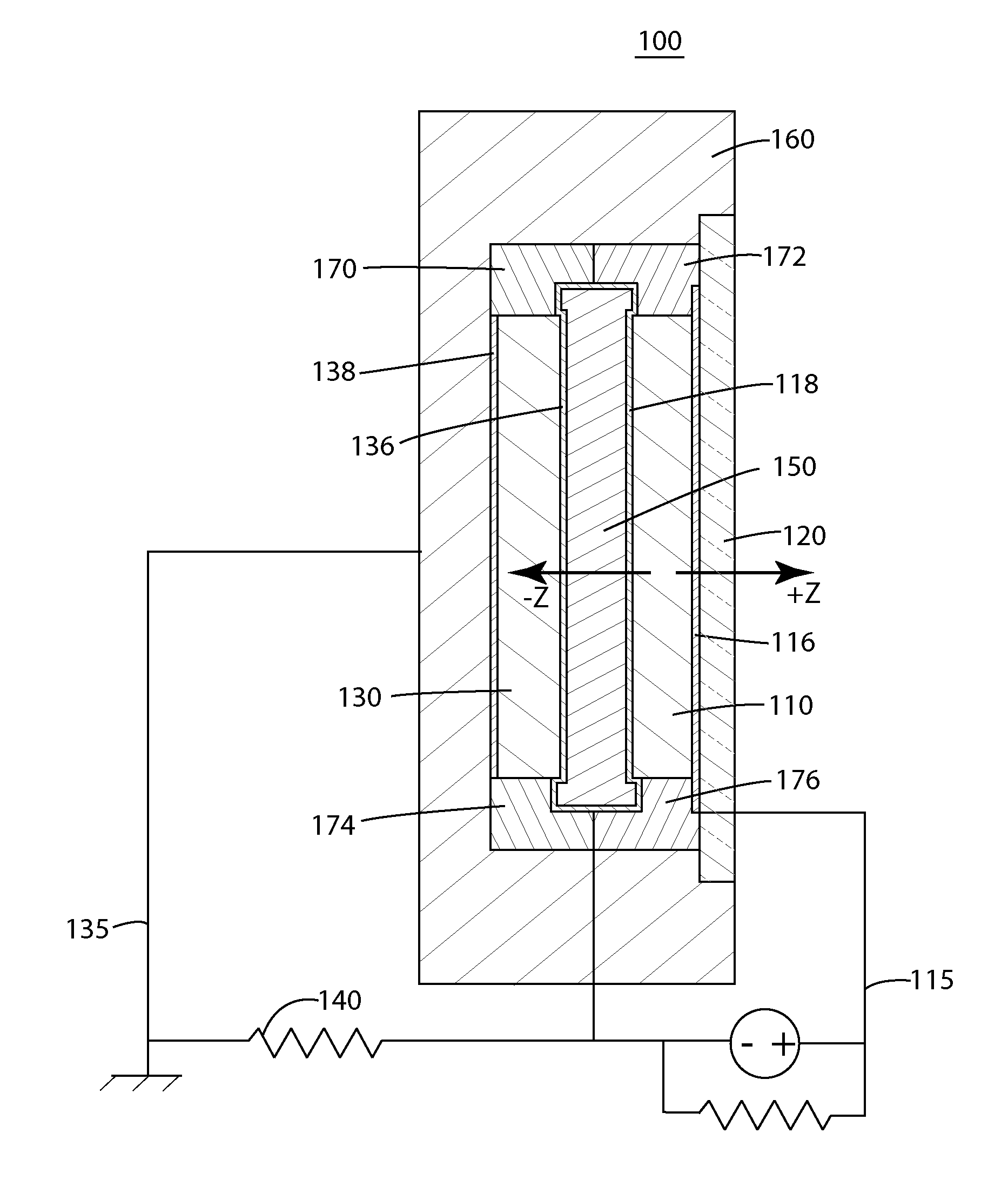
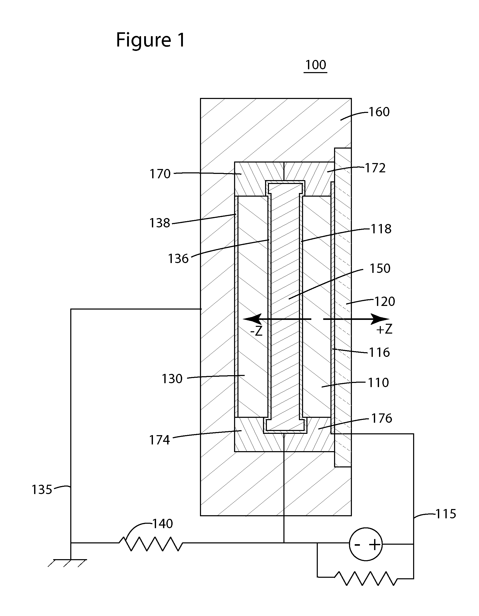
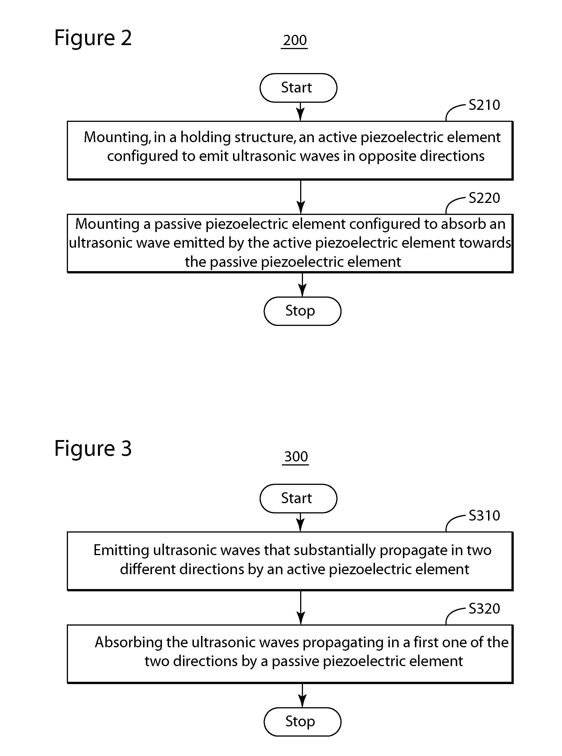
[0010]According to another exemplary embodiment, an ultrasonic transducer includes an active piezoelectric element, a passive piezoelectric element, a first electrical circuit, a second electrical circuit, and a housing. The active piezoelectric element is configured to receive an electrical signal and to covert the received electrical signal into a first ultrasonic wave propagating in a first direction and a second ultrasonic wave propagating in a second direction different from the first direction. The passive piezoelectric element is located and configured to absorb a remaining part of the second ultrasonic wave that reaches the passive piezoelectric element, and is configured to convert the absorbed second ultrasonic wave into an electrical

Problems solved by technology

Differentiation of echoes of the spherical wave that are reflected from different directions is impractical.
However, the issue of back-propagating waves has not been solved in a satisfactory manner.
Due to the large absorber, such a transducer is heavy and bulky.

Method used


Image

  • Mono-directional Ultrasound Transducer for Borehole Imaging
  • Mono-directional Ultrasound Transducer for Borehole Imaging
  • Mono-directional Ultrasound Transducer for Borehole Imaging

Examples


Embodiment Construction

[0017]The following description of the exemplary embodiments refers to the accompanying drawings. The same reference numbers in different drawings identify the same or similar elements. The following detailed description does not limit the invention. Instead, the scope of the invention is defined by the appended claims. The following embodiments are discussed, for simplicity, with regard to the terminology and structure of a transducer usable in a borehole of a well drilled for oil and gas. However, the embodiments to be discussed next are not limited to these systems, but may be applied to other systems that require the supply of a mono-directional ultrasonic transducer.

[0018]Reference throughout the specification to “one embodiment” or “an embodiment” means that a particular feature, structure, or characteristic described in connection with an embodiment is included in at least one embodiment of the subject matter disclosed. Thus, the appearance of the phrases “in one embodiment” ...


PUM

PropertyMeasurementUnit
Electric energyaaaaaaaaaa
Thicknessaaaaaaaaaa
Electrical resistanceaaaaaaaaaa

Abstract

Devices and methods to generate a mono-directional ultrasonic wave are provided. An ultrasonic sensor configured to emit a substantially mono-directional ultrasonic wave includes a first piezoelectric element and a second piezoelectric element. The first piezoelectric element is configured to generate a first ultrasonic wave propagating in a first direction and a second ultrasonic wave propagating in a second direction which is different from the first direction. The second piezoelectric element is located and configured to absorb the second ultrasonic wave, and is configured to convert an energy of the absorbed second ultrasonic wave into an electrical energy.

Description

BACKGROUND[0001]1. Technical Field[0002]Embodiments of the subject matter disclosed herein generally relate to ultrasonic transducers and ultrasonic methods usable for borehole imaging, more particularly, to devices and techniques using a piezoelectric element to absorb backwards ultrasonic waves.[0003]2. Discussion of the Background[0004]Since oil and gas remain a source of energy that cannot be replaced at a significant enough proportion in the world economy, the interest in developing new production fields has continued to increase, in spite of the harsher conditions in terms of accessibility and safety of exploitation. Ultrasonic measurements inside oil and gas wells are often desirable because they give access to information related to the size and configuration of a well casing, sides of the well, etc. In order to collect this information, a probe or “sonde” having one or more ultrasonic transducers attached may be lowered into the borehole inside the casing or prior to the in...

Claims


Application Information

Patent Timeline
IPC IPC(8): H04R17/00H01L41/22G10K9/125
CPCB06B1/0611Y10T29/42G10K11/002
Inventor KENNEDY, SCOTT
Owner SONDEX WIRELINE
Learn More