
Multi-sensor video frame synchronization apparatus and methods

a multi-sensor, video frame technology, applied in the direction of color television details, television system details, television systems, etc., can solve the problems of loss of perceived depth, loss of 3-d effect, visual cues may become confused,

Active Publication Date: 2012-06-28
TEXAS INSTR INC
View PDF1 Cites 31 Cited by
  • Summary
  • Abstract
  • Description
  • Claims
  • Application Information

AI Technical Summary

Benefits of technology

The patent text is submitted to comply with a requirement for an abstract that allows quick understanding of the technical disclosure. The text is organized in a way that features are grouped together to make the disclosure easier to read. The claims are incorporated into the text, each claim standing on its own as a separate embodiment. The technical effect of this method of disclosure is that it allows for more features to be included in a single embodiment without requiring additional information to be added.

Problems solved by technology

Lack of synchronization between frames may result in a loss of perceived depth, that is, loss of the 3-D effect.
Visual cues may become confused if an object's location is seen as different between the left and right views at the time of capture.
Control logic associated with such image sensors may not provide for synchronization of frames from multiple image sensors.
The absence of multi-sensor frame synchronization may result in unacceptable stereoscopic video quality as described above.

Method used


Image

  • Multi-sensor video frame synchronization apparatus and methods
  • Multi-sensor video frame synchronization apparatus and methods
  • Multi-sensor video frame synchronization apparatus and methods

Examples


Embodiment Construction

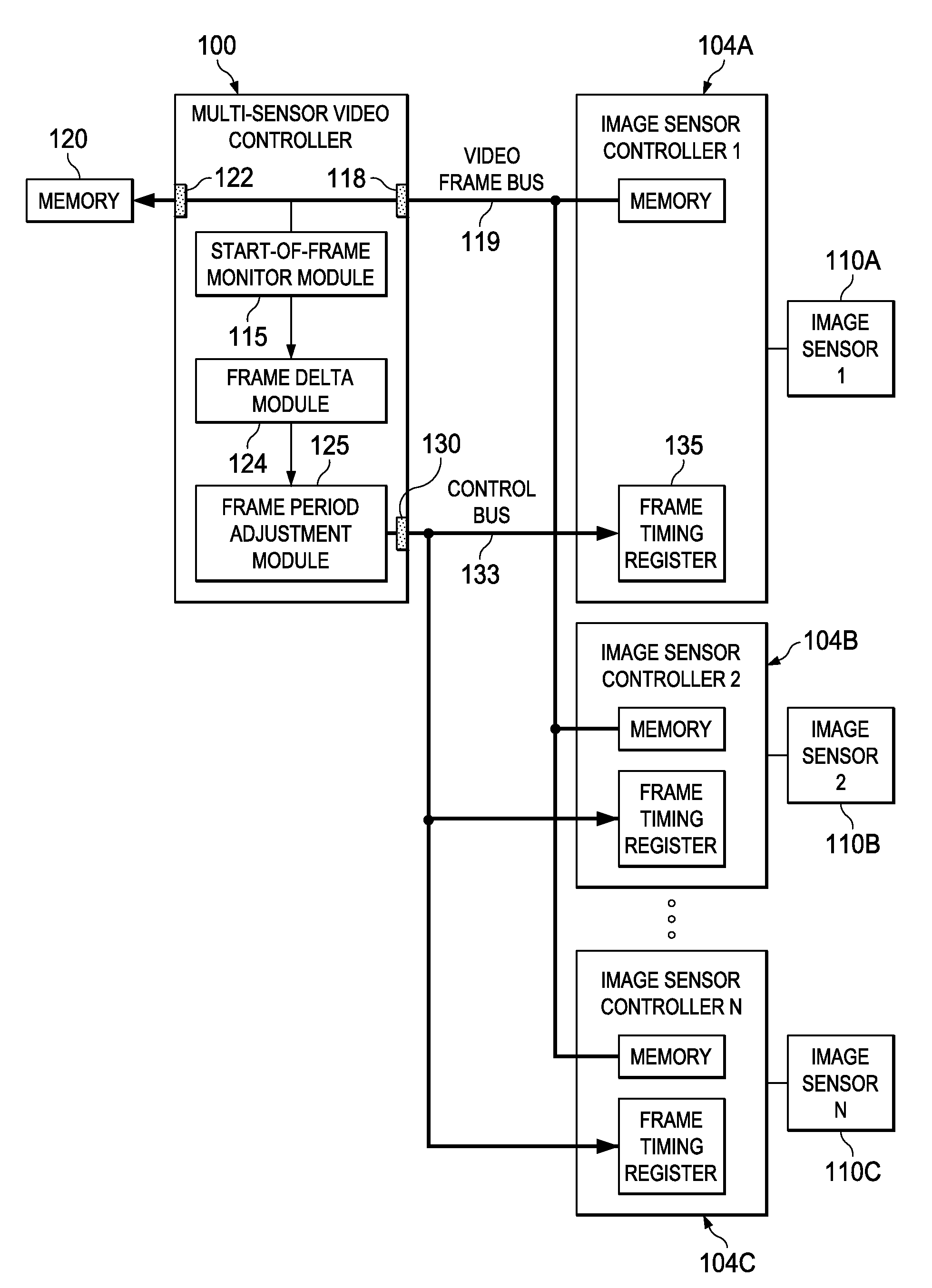
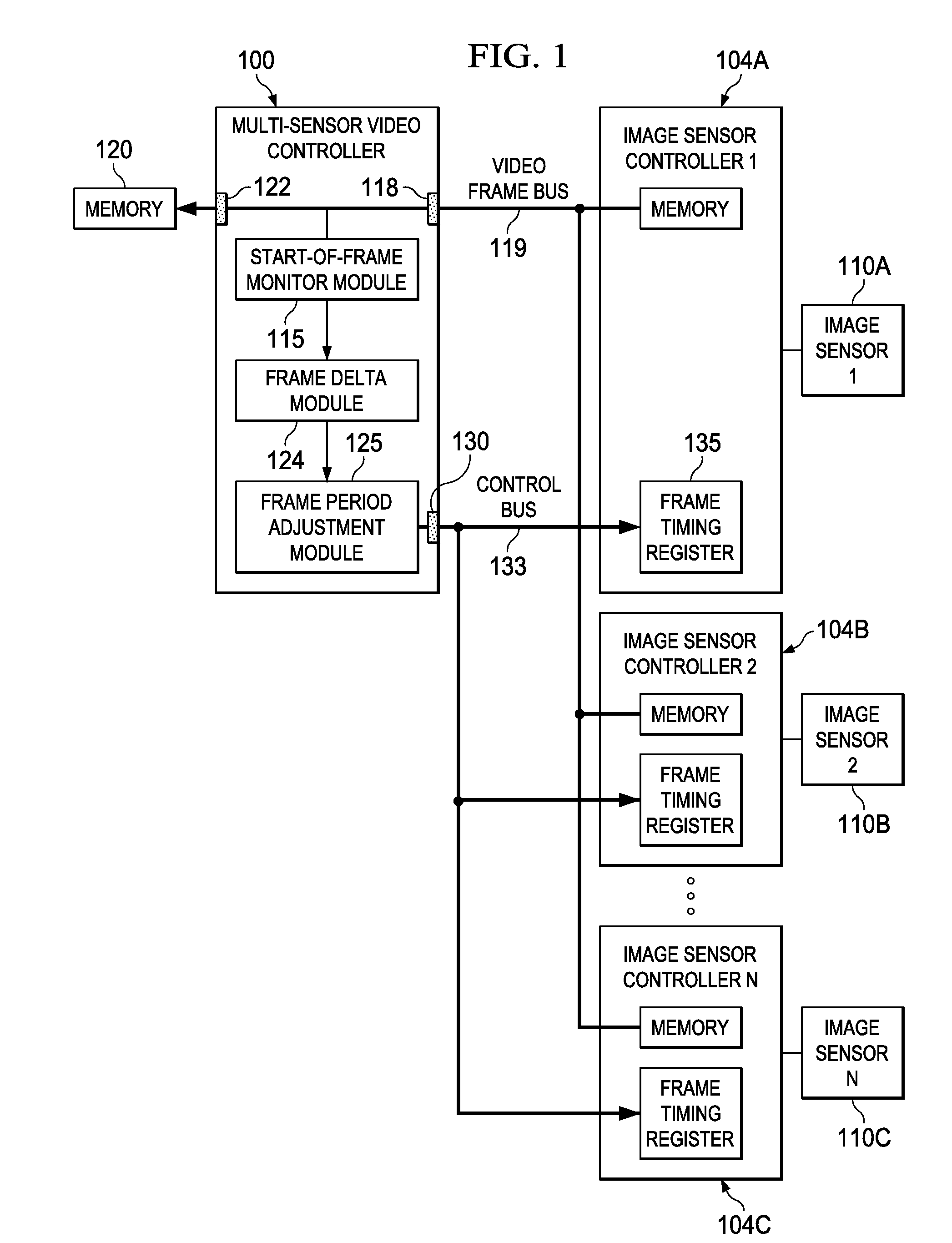
[0011]FIG. 1 is a block diagram of a multi-sensor video controller 100 within an imaging system according to various example embodiments of the current invention. The video controller 100 provides image sensor parameter setup information to two or more image sensor controllers 104A, 104B, and 104C (collectively, “image sensor controllers 104”). Each of the image sensor controllers 104 supplies low-level timing and control signals to a corresponding image sensor 110A, 110B, or 110C (collectively, “image sensors 110”). The image sensor controllers 104 also provide a stream of video frames, status, and synchronization signals back to the multi-sensor video controller 100.

[0012]The video controller 100 includes a start-of-frame monitor module 115. The start-of-frame monitor module 115 monitors times of receipt of start-of-frame indications associated with frames from each of the image sensors 110. The video controller 100 also includes a video frame bus interface 118 operationally coupl...


PUM


Abstract

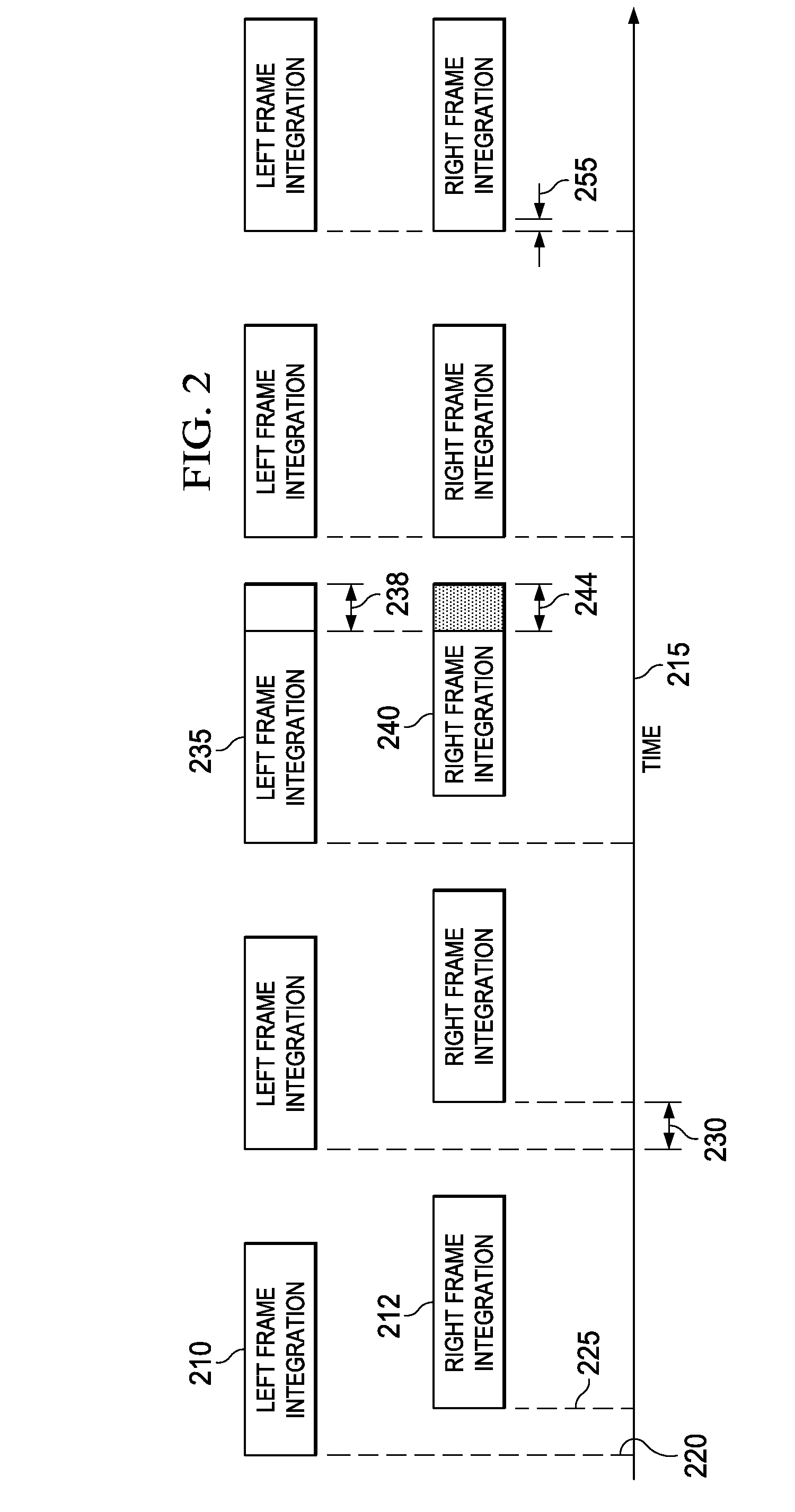
Apparatus and methods disclosed herein operate to monitor times of receipt of start-of-frame indications associated with frames received from multiple image sensors at a video controller. Time differences between the times of receipt of the frames are calculated. Embodiments herein alter one or more frame period determining parameter values associated with the image sensors if the time differences equal or exceed frame synchronization hysteresis threshold values. Parameter values are adjusted positively and / or negatively to decrease the time differences. The parameter values may be reset at each image sensor when the time differences become less than the frame synchronization hysteresis threshold value as additional frames are received at the video controller.

Description

TECHNICAL FIELD[0001]Embodiments described herein relate to apparatus and methods associated with digital imaging, including structures and methods associated with video frame synchronization.BACKGROUND INFORMATION[0002]Some methods of stereoscopic image and video capture, sometimes referred to as “three-dimensional” (3-D) imaging, use two or more image sensors to capture a scene. Each image sensor captures the scene from a slightly different angle according to the amount of spacing between the image sensors.[0003]In the case of stereoscopic video, good results may be obtained when the frames captured by each image sensor are synchronized. Lack of synchronization between frames may result in a loss of perceived depth, that is, loss of the 3-D effect. Visual cues may become confused if an object's location is seen as different between the left and right views at the time of capture.[0004]Commercially available image sensors are typically packaged with a sensor controller. Precise tim...

Claims


Application Information

Patent Timeline
Patent Type & Authority Applications(United States)
IPC IPC(8): H04N5/04H04N13/239H04N13/243
CPCH04N13/0051H04N13/0239H04N13/0044H04N13/0296H04N13/0242H04N13/239H04N13/158H04N13/167H04N13/243H04N13/296
Inventor HEWES, GREGORY ROBERTWARE, JR., FRED WILLIAM
Owner TEXAS INSTR INC
Learn More