
Retrograde entry antegrade placement for femoral artery access

a technology for femoral arteries and antegrade placement, which is applied in the direction of applications, ultrasonic/sonic/infrasonic diagnostics, catheters, etc., can solve the problems of crimping or, worse, laceration, and insurmountable technical challenges in the antegrade approach to a large patien

Active Publication Date: 2012-05-24
POLR ANGIOSCI LLC
View PDF1 Cites 4 Cited by
  • Summary
  • Abstract
  • Description
  • Claims
  • Application Information

AI Technical Summary

Benefits of technology

"The patent describes a method and device for treating lower extremity arterial disease by placing endovascular devices in a retrograde manner and then moving them in an antegrade direction. This technique helps to improve blood flow and can be performed using minimally invasive procedures."

Problems solved by technology

Body habitus is frequently abnormal in patients undergoing treatment for vascular disease.
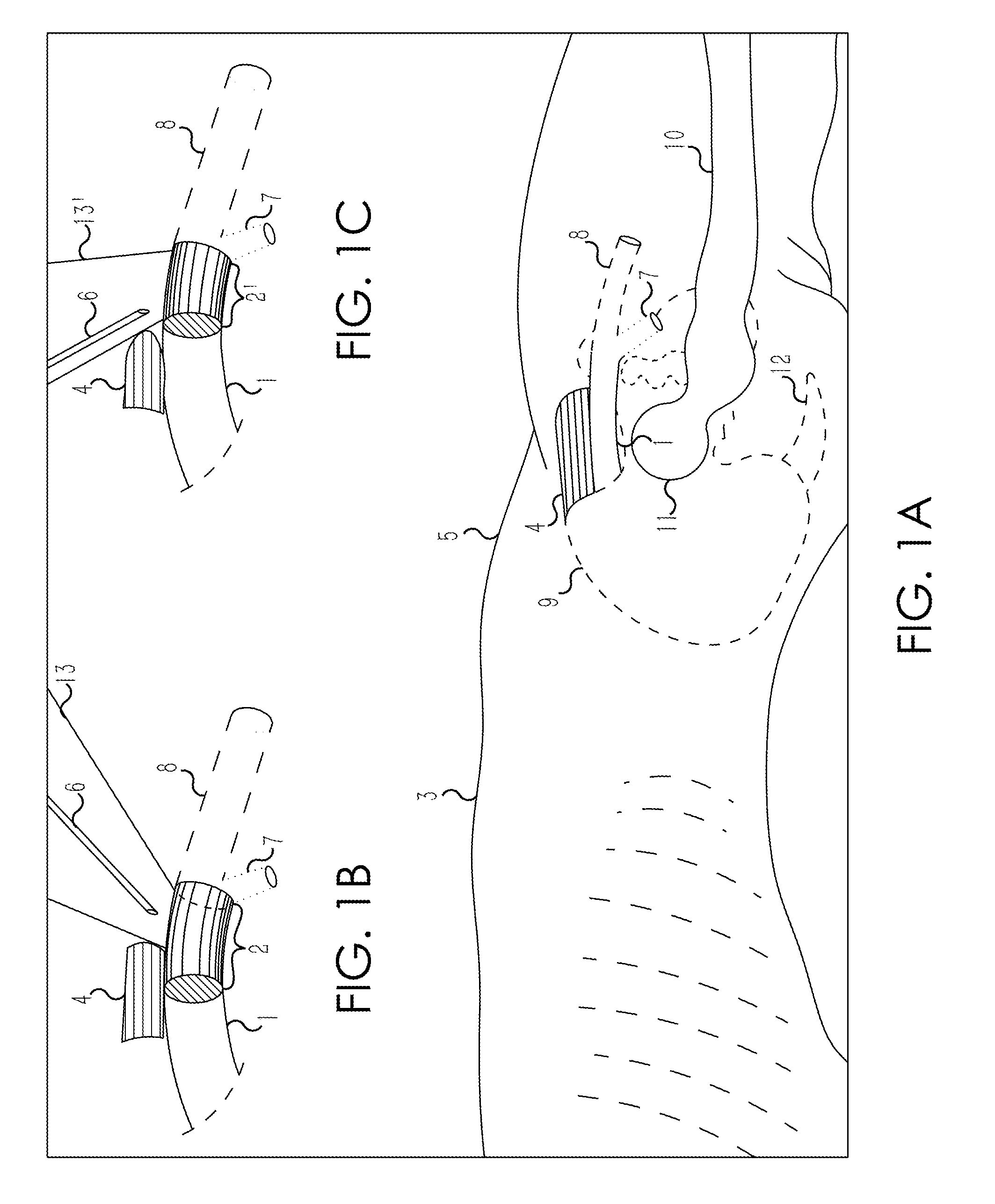
Because CFA 1 Target Segment 2′ is also reduced in length, the technical challenges in the antegrade approach to a large patient are often insurmountable.
If much steeper, 60 to 90 degrees, the subsequent placement of larger bore devices will lead to crimping or, worse, laceration (“cheese-wire” effect) of the arterial wall, with hemorrhage.
Operators have long experienced the ease with which the retrograde stick approach places a wire almost unfailingly in the iliac system.
Intentional entry into SFA 8 for placement of larger (5 French or greater) devices, is problematic.
Surgeons will often find the SFA 8 wall friable and unforgiving when it is sutured, a problem compounded by the artery's smaller lumen.
The catheter interventionalist placing a sheath in an artery faces an additional problem.
Given two tubes, one larger and one smaller, a slit of the same length made transversely in each will disrupt shape-retention properties and tubular integrity much more in the smaller than in the larger tube.
This is likely due in part to the difficulty in compressing SFA 8 manually after sheath removal.
Anatomy of the femoral zone is complex and can be deceiving to the unschooled.
But in heavier bulkier individuals the mounding and angulation of tissue can present formidable obstacles.
Antegrade access is not widely touted in the literature, nor utilized extensively, due to its technical difficulty.
Schneider noted that even the easier, retrograde approach resulted in less than optimal needle placement in 56% of cases, including 13% entirely beyond the borders of CFA 1.
As a result of these and other problems, operators have not embraced antegrade femoral access.
Manufactured devices for precise work in the lower extremities—particularly if utilized to treat targets below the knee—tend to be difficult to maneuver when working over the distances and past the multiple twisting turns involved in the retrograde up-and-over access technique.
However, the increased length sacrifices pushability and control.
This is not only mechanically disadvantageous, but requires “opposite-think” and 3-dimensional conceptual efforts which are not always easy for an operator.
As a result, widespread application of certain devices has been limited by difficulty in controlling the catheters at distant lesions.
Because of the predominant pattern of retrograde femoral access, manufacturers have been forced to compromise device control for length, and performance has suffered.
Effective therapeutic devices which function optimally in the antegrade direction have thus been hindered in reaching a patient population which could benefit by their use.

Method used


Image

  • Retrograde entry antegrade placement for femoral artery access
  • Retrograde entry antegrade placement for femoral artery access
  • Retrograde entry antegrade placement for femoral artery access

Examples


Embodiment Construction

[0072]Retrograde Entry Antegrade Placement (REAP) For SFA Access

[0073]The following will describe various apparatus and various method steps utilized in retrograde entry for antegrade placement of endovascular devices via SFA access.

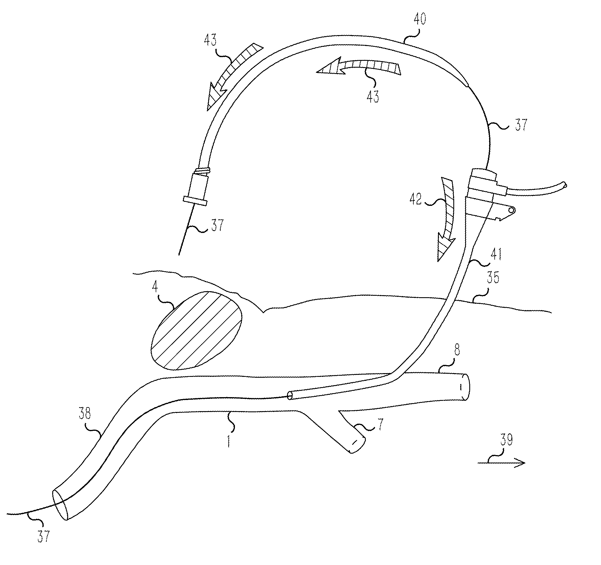
[0074]Step 1. FIG. 8A shows the operator, patient, and equipment in alternate positions. Referring now to FIG. 8A, Operator 29 is positioned on Patient 30's right side, as for any traditional femoral artery entry angiographic procedure. The C-Arm X-Ray Machine 31 may be positioned opposite or adjacent to Operator 29 and is movable in the directions indicated by the arrows. C-Arm X-Ray Machine 31 is used to perform fluoroscopic and angiographic imaging. Monitors 32 are positioned at the patient's left, at torso level. Referring now to FIG. 8B, ultrasound is used to acquire data including the distance from Skin 35 to CFA 1, the lumen diameter of CFA 1, and location of the orifice of the take-off of PFA 7 and the location of the origin of CFA 1. Operator 29...


PUM


Abstract

A Retrograde Entry Antegrade Placement (REAP) method and apparatus facilitate the antegrade (i.e., in the direction of blood flow) placement of endovascular devices for treatment of lower extremity arterial disease. Initially, a retrograde entry is made into the arterial system of a patient at an entry point with a curved needle, which then exits at an exit point proximal to the entry point, with a first wire then passed through the lumen of the curved needle. From the skin exit point, a Dual-Lumen Access Director (DAD) device is advanced in the antegrade direction down the first wire in a first lumen and enters the CFA 1 lumen. A second wire is passed down a second lumen in the DAD device and follows the SFA lumen in the antegrade direction. The DAD device is removed, and a standard dilator sheath is inserted over the second wire and the endovascular treatment begins.

Description

CROSS-REFERENCES TO RELATED APPLICATIONS[0001]This application claims the benefit of U.S. Provisional Application Ser. No. 61 / 415,188 filed on Nov. 18, 2010 titled “Retrograde Access Antegrade Placement For Femoral Artery Access” and U.S. Provisional Application Ser. No. 61 / 444,928 filed on Feb. 21, 2011 titled “Retrograde Entry Antegrade Placement For Femoral Artery Access” both of which are incorporated herein by reference in their entirety for all that is taught and disclosed therein.BACKGROUND[0002]1. Rationale for Choice of the Femoral Artery in Vascular Access[0003]The common femoral artery is the primary entry site for interventional vascular access. The majority of procedures involving interventions upon major arteries, including those of the limbs, neck, viscera, heart and head, are performed through needle entry into the common femoral artery. In the vast majority of cases, certainly greater than 95% in the USA, needle entry into the common femoral artery is done via a ret...

Claims


Application Information

Patent Timeline
Patent Type & Authority Applications(United States)
IPC IPC(8): A61B17/34A61B6/00
CPCA61B17/06109A61M25/065A61B2017/3413A61B2017/22038A61B6/12A61B6/485A61B8/0841A61B17/0218A61B17/3403A61B17/3415A61B17/3423A61B17/3478A61B2017/00778A61B2017/3405A61B2017/3425A61B2017/3454A61M39/02A61M2210/12
Inventor CONN, JOHN MILLER
Owner POLR ANGIOSCI LLC
Learn More