
Tire with foamed noise damper

a technology of foamed noise dampers and tires, which is applied in the direction of transportation and packaging, other domestic articles, coatings, etc., can solve problems such as road nois

Inactive Publication Date: 2012-05-24
BORMANN RENE LOUIS +2
View PDF3 Cites 29 Cited by
  • Summary
  • Abstract
  • Description
  • Claims
  • Application Information

AI Technical Summary

Problems solved by technology

One source of road noise is resonance within the air chamber enclosed by the innermost surface of the tire and the rim.

Method used


Image

  • Tire with foamed noise damper
  • Tire with foamed noise damper

Examples


Embodiment Construction

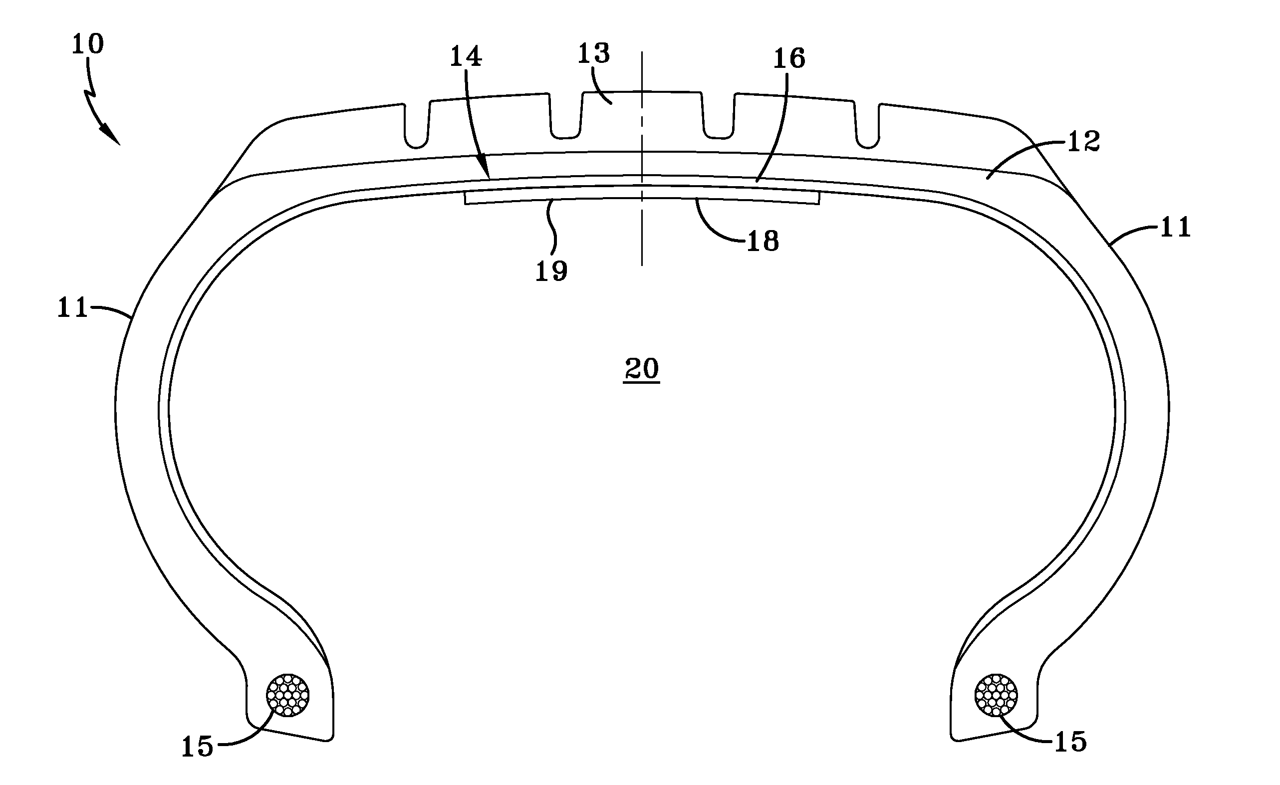
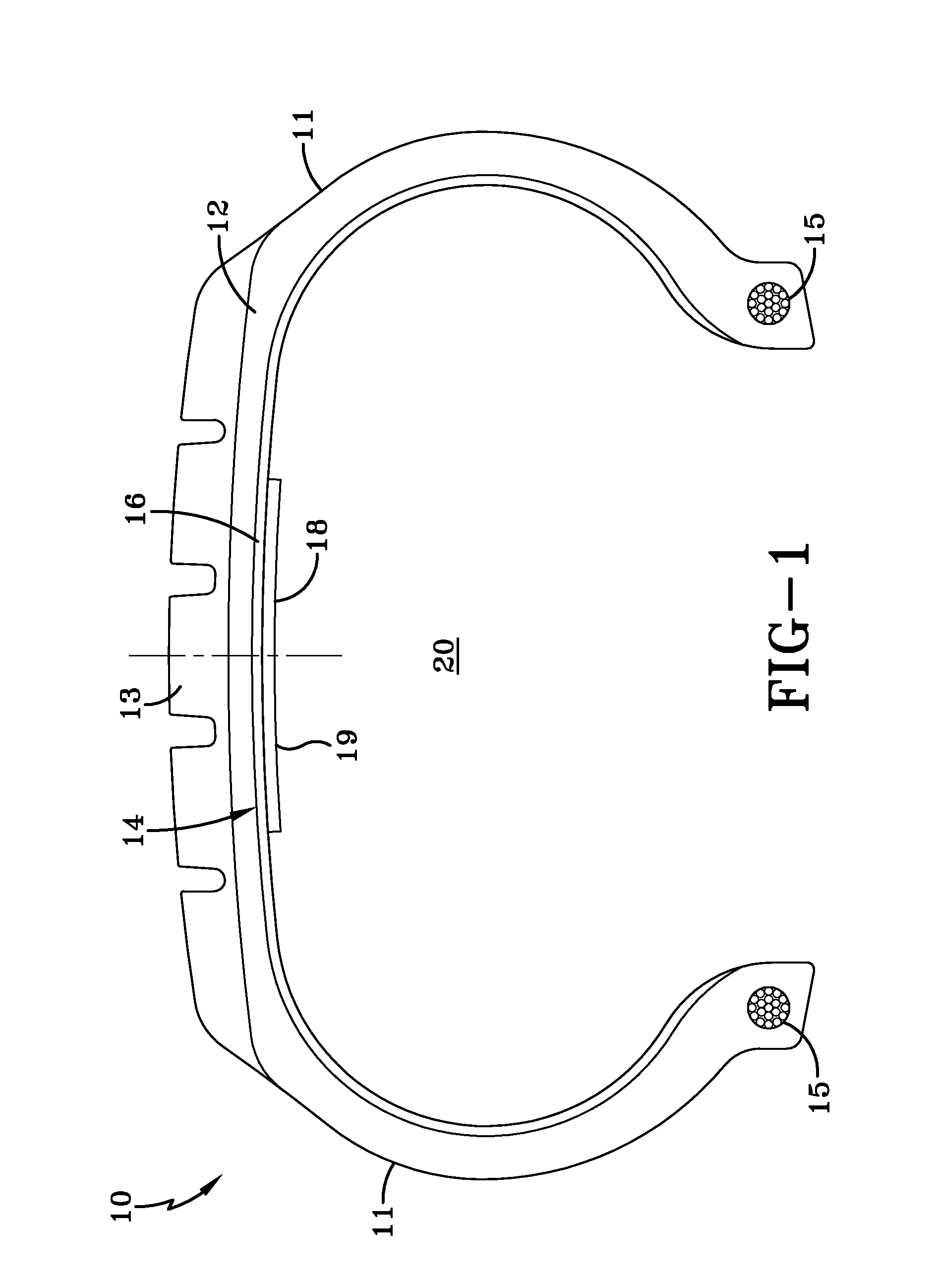
[0013]In accordance with the present invention, there is provided a method for making a tire having a foam noise damper, comprising the steps of: obtaining a tire having an innerliner, the innerliner having a surface facing an interior cavity of the tire; applying a foamable liquid to the surface; and foaming the foamable liquid to form a solid foam noise damper secured to the tire innerliner.

[0014]There is further provided a pneumatic tire comprising two spaced inextensible beads; a ground contacting tread portion; a pair of individual sidewalls extending radially inward from the axial outer edges of said tread portion to join the respective beads, the axial outer edges of the tread portion defining a tread width; a supporting carcass for the tread portion and sidewalls; an innerliner disposed radially inward of the carcass, the innerliner having a surface exposed to an inner cavity of the tire; and a foamed noise damper disposed on the surface of the innerliner; the foamed noise d...


PUM

PropertyMeasurementUnit
specific gravityaaaaaaaaaa

Abstract

The present invention is directed to a method for making a tire having a foam noise damper, comprising the steps of: obtaining a tire having an innerliner, the innerliner having a surface facing an interior cavity of the tire; applying a foamable liquid to the surface; and foaming the foamable liquid to form a solid foam noise damper secured to the tire innerliner.

Description

BACKGROUND OF THE INVENTION[0001]Government regulations and consumer preferences continue to compel a reduction in the acceptable noise levels produced from the tires of passenger vehicles. One source of road noise is resonance within the air chamber enclosed by the innermost surface of the tire and the rim. One type of effort to reduce tire noise is damping the sound from the air vibration in the air chamber, which efforts have focused mainly on altering the innermost surface of the tire adjacent the tire carcass. Shortcomings in these previous efforts, as well as new stricter regulations regarding noise reduction, have provided a need for further improvements to the tire to reduce sound transmission due to vibrations within the air chamber.SUMMARY OF THE INVENTION[0002]The present invention is directed to a method for making a tire having a foam noise damper, comprising the steps of: obtaining a tire having an innerliner, the innerliner having a surface facing an interior cavity o...

Claims


Application Information

Patent Timeline
Patent Type & Authority Applications(United States)
IPC IPC(8): B60C19/00B29D30/08B60C5/00
CPCB29D30/0662B29D30/0681B60C19/002
Inventor BORMANN, RENE LOUISAGOSTINI, GIORGIOMAJUMDAR, RAMENDRA NATH
Owner BORMANN RENE LOUIS
Learn More