Box Having Foldable and Dismantlable Exterior Walls

Active Publication Date: 2012-05-17
IFCO SYST GMBH
View PDF4 Cites 7 Cited by
  • Summary
  • Abstract
  • Description
  • Claims
  • Application Information

AI Technical Summary

Benefits of technology

[0011]In some further embodiments of the invention, the carrying capacity or stability of the resulting connection is additionally increased by the fact that the cam opening also comprises an opening section passing in the vertical direction and a lateral opening section passing in the lateral direction, wherein the cam has an exterior contour or is geometrically implemented so that in the up-folded state an element of the cam or a recess in the cam engages the lateral opening section of the cam opening during up-folding. By this, the cam is also prevented from sliding upwards out of the cam opening with a tensile stress, by the massive material of the floor located above the lateral opening section of the cam opening. Thus, the cam in the cam opening in the up-folded state may also additionally receive weight or carry an additional load which increases the stability or strength of the foldable box in this embodiment. Here, in some further embodiments of the present invention, the cam opening comprises such a cross-section in the vertical direction that the cam in the down-folded state of the side wall may be removed upwards from the cam opening so that also in the embodiment in which the cam may carry additional load, the exterior wall may be dismantled in the down folded state without any tools. In some embodiments, the geometry is selected such that both the cam opening and also the guide opening extend in the lateral direction outwards up to a common exterior wall so that the same in other words comprise identical dimensions in the lateral direction. In the direction perpendicular to the vertical and the lateral direction, the cam opening or the guide opening in some embodiments comprise dimensions which are slightly larger than the horizontal extension of the shaft or the horizontal extension of the cam in order to enable a connection free of play also in this dimension between the exterior wall and the floor or the fixed exterior wall area of the floor. In other words, the horizontal extension of the guide opening and the cam opening basically corresponds to the horizontal dimensions of the shaft or the cam, wherein the horizontal extension of the openings is slightly larger, for example by 0.5 mm or by 1 mm.
[0027]With some embodiments of the present invention, several convex surface areas in a wall are used which are interconnected by an arrangement of ribs and bridges perpendicular to the ribs extending across the height of the exterior wall to connect the per se stable convex surface areas without high material expense in a very torsion resistant way, so that an all-in-all very robust structure with a low wall strength results. In some embodiments of the present invention, the bridges and the ribs are exclusively arranged on the outside of the exterior wall so that the stiffening effects are achieved without hygiene suffering by food getting caught in the sharp edges of the ribs and bridges in the interior of the box. In some embodiments of the present invention, any hinge arrangements connecting the exterior wall to the floor of the foldable box are basically arranged in areas in which the bridges are located between the spherical surfaces. As the bridges extending across the height of the exterior wall are those structures which may carry the greatest tensile stress, by the produced arrangement of the hinge elements a structure or an exterior wall is generated comprising the highest possible stability requirements also regarding power transmission or force transmission to the floor and it simultaneously only necessitates a thin material-saving exterior wall which is flat or smooth at the interior side and thus easy to clean.

Problems solved by technology

Simultaneously, the box ought to be stable, which makes the use of large flat planes difficult.
Further, the boxes are also used several times according to their purpose which even increases requirements regarding robustness.
However, additionally, the possibility of a wrong operation should be considered, i.e., that a force acts upon the locking mechanism without the same being operated.
Thus, after exceeding this force, i.e., after completely erecting the exterior wall, the exterior wall is held in the upright position as the force acting in the upright position between the underside of the exterior wall and the fixed exterior wall area is smaller and the exterior wall may thus not overcome the internal edge area by simply folding down by the weight force of the exterior wall without external force.
Such clamps, in particular when using plastics parts, are subject to wear and tear, so that the inhibition of movement and thus the functionality of the side wall is automatically reduced over time.
This leads to losses regarding speed and reliability of handling which may be prevented by vertical locking mechanisms.
The use of an individual spherical surface as a side wall, with extensive side walls, would thus not have a large effect supporting stability.

Method used


Image

  • Box Having Foldable and Dismantlable Exterior Walls
  • Box Having Foldable and Dismantlable Exterior Walls
  • Box Having Foldable and Dismantlable Exterior Walls

Examples


Embodiment Construction

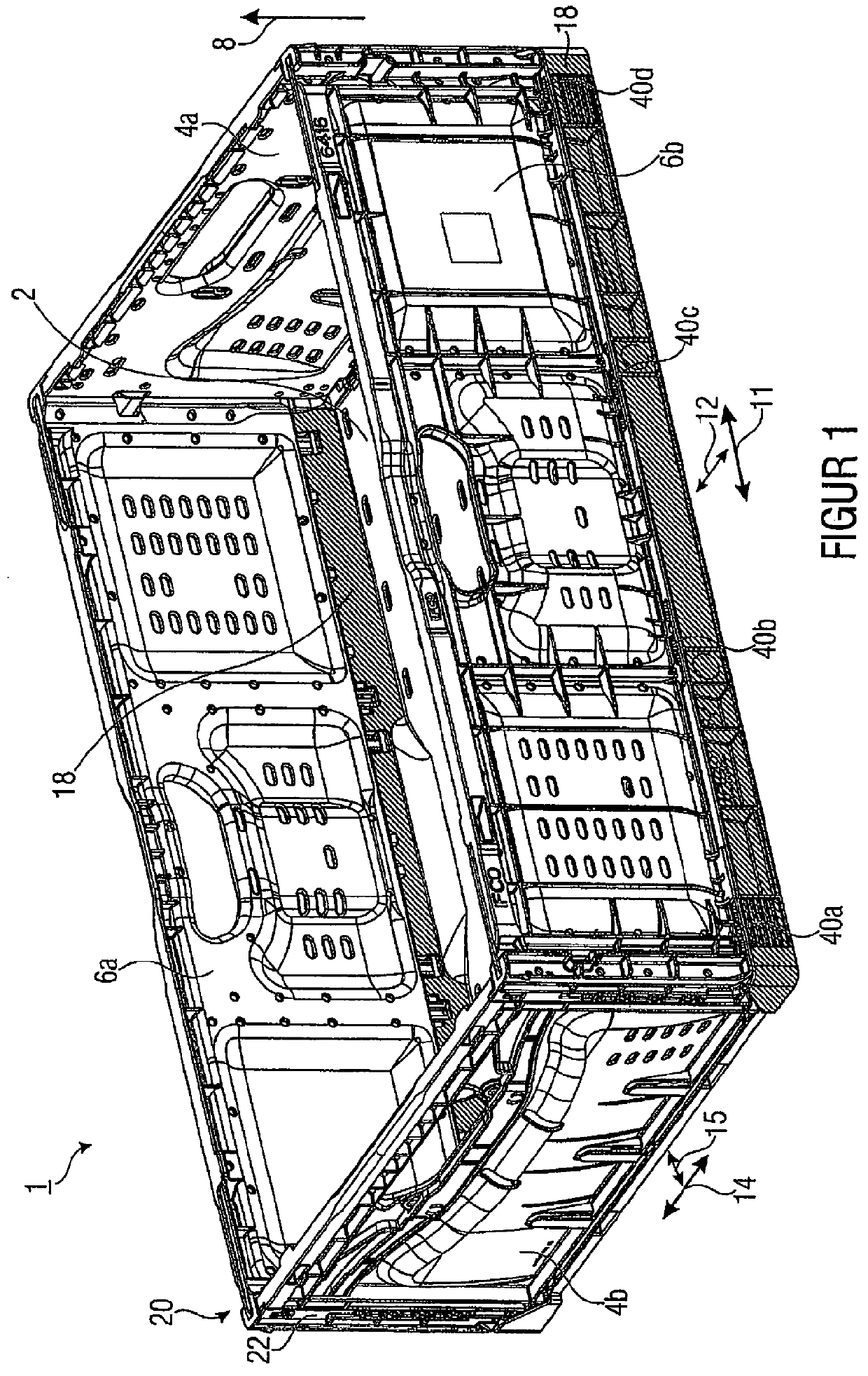
[0047]FIG. 1 shows a semi-perspective view of an embodiment of a foldable box 1. Here, a foldable box 1 within the scope of this description is a box or a crate which is open in one direction (in the vertical direction to the top) and which comprises a floor and four exterior or side walls which are connected to the floor such that they may be moved or up-folded or down-folded with respect to the floor. In the down-folded state, i.e., when all four walls are folded onto the floor, the box only has a low building height and is easily transportable.

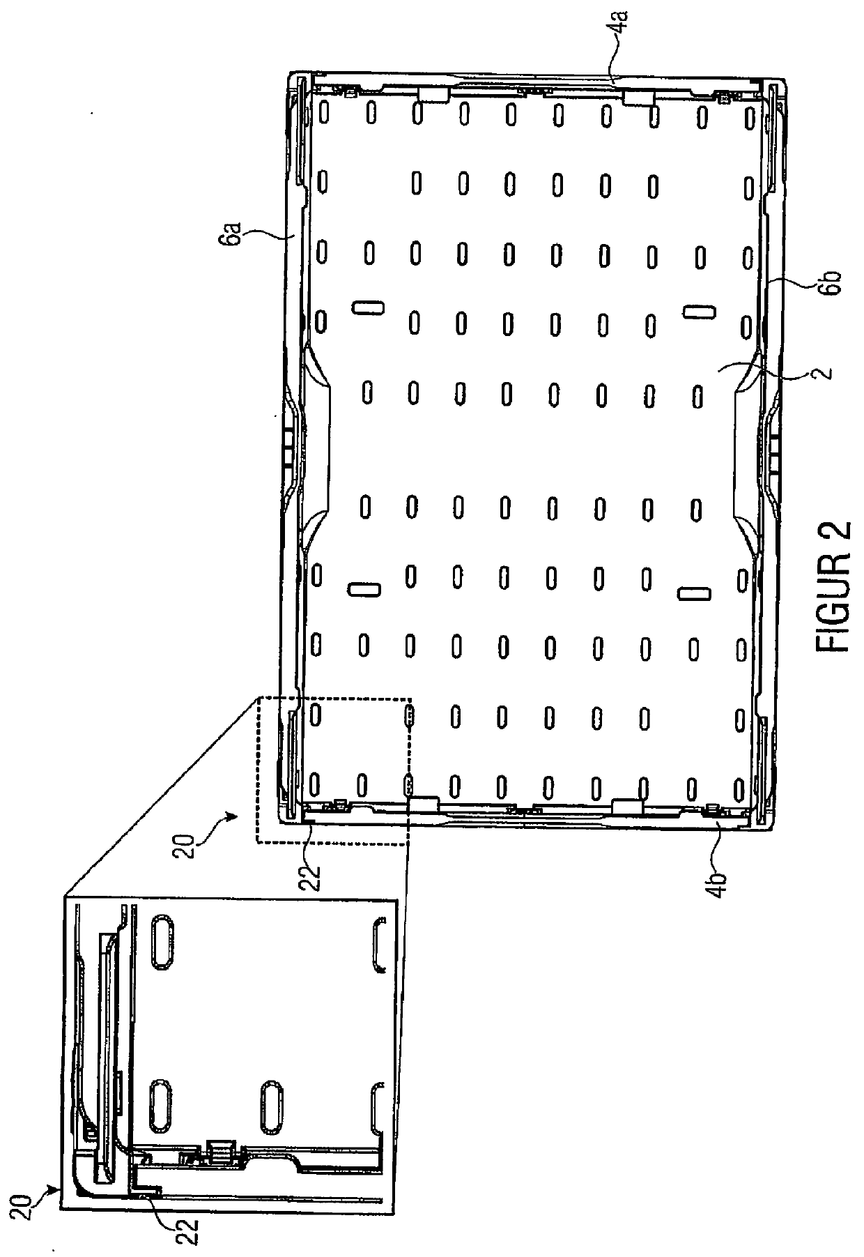
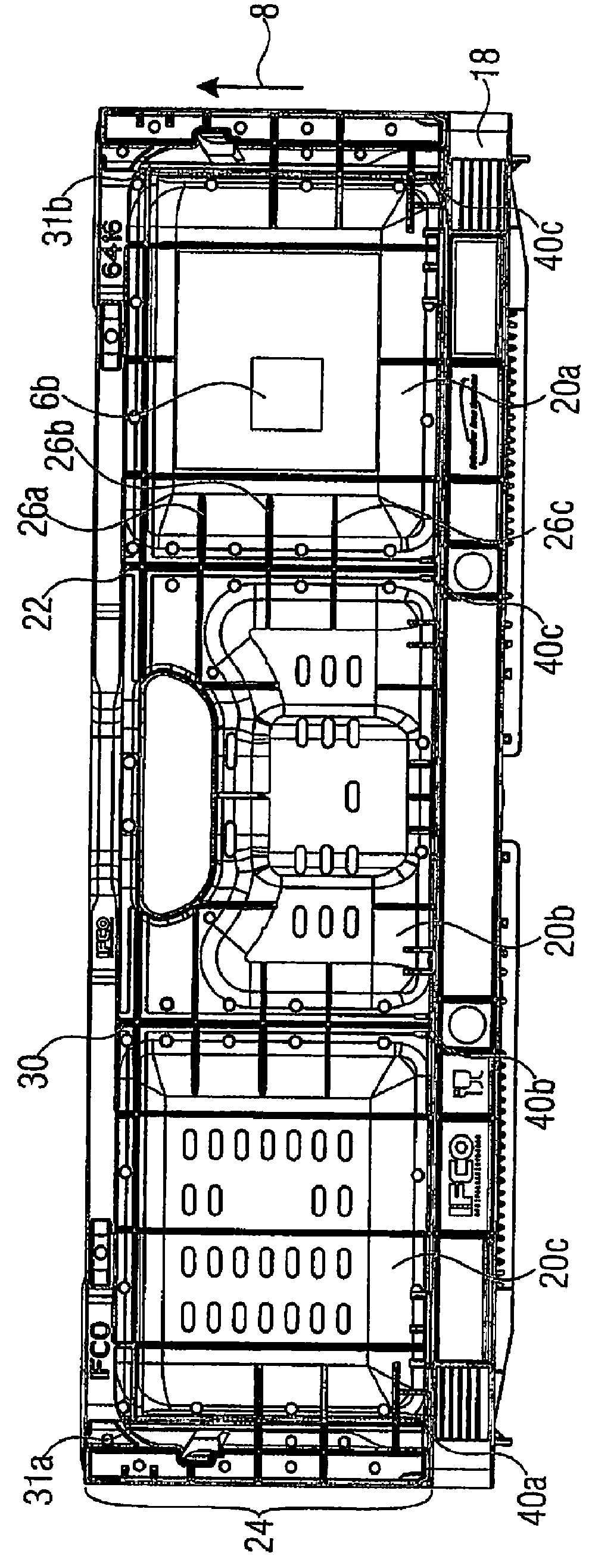
[0048]The foldable box of FIG. 1 thus comprises a floor, pairs of opposing transverse side exterior walls 4a and 4b and pairs of opposing longitudinal side exterior walls 6a and 6b. It is to be noted here, that for identifying the exterior walls in the following description the exterior walls are to be designated as longitudinal side exterior walls which have a larger extension than the transverse side exterior walls. This is not to be rega...


PUM


Abstract

A foldable box includes a floor having a fixed exterior wall extending from the floor in a vertical direction upwards and an exterior wall having a shaft arranged in the base area of the exterior wall. The foldable box further includes a guide opening in the fixed exterior wall area in which the shaft is arranged, the guide opening including an opening section extending basically in the vertical direction through which the shaft may be guided out from the top, and a lateral opening section extending in a lateral direction from an outside of the fixed exterior wall area inwards, in which the shaft may be shifted basically in a lateral direction. A cam arranged in the base area of the exterior wall has a cam contour which is implemented such that the cam contour, when erecting the exterior wall, gets into contact with a contact surface arranged at the fixed exterior wall area such that the shaft is moved inwards in the lateral opening section.

Description

CROSS-REFERENCE TO RELATED APPLICATIONS[0001]This application is a continuation of copending International Application No. PCT / EP2010 / 054903, filed Apr. 14, 2010, which is incorporated herein by reference in its entirety, and additionally claims priority from International Application No. PCT / EP2009 / 002760, filed Apr. 15, 2009, and from German Applications Nos. DE 10 2009049103.1, filed Oct. 13, 2009 and DE 102009034451.9, filed Jul. 23, 2009, which are all incorporated herein by reference in their entirety.BACKGROUND OF THE INVENTION[0002]The present invention relates to easily transportable boxes whose side walls may be folded down for transport and whose side walls are easily dismantlable by using a special hinge arrangement and may simultaneously receive a substantial load in the upfolded state.[0003]On the market place, a plurality of foldable boxes or foldable crates is available consisting of a bottom or floor and side walls which are foldable with respect to the floor so tha...

Claims


Application Information

Patent Timeline
IPC IPC(8): B65D6/22
CPCB65D11/1833B65D11/22B65D11/20B65D11/1866
Inventor ORGELDINGER, WOLFGANG
Owner IFCO SYST GMBH
Why Eureka
Try Eureka