
Collapsible Adjusting Funnel Stand

a funnel and adjusting technology, applied in the field of collapsible adjusting funnel stands, can solve the problems of easy tipping, material can quickly build up in the funnel and spill, and the vertical adjustment funnel holders that extend the vertical supporting member using tubes or sliding arms are not conducive to operation with only one hand, so as to eliminate bulk, weight, and friction resistance. the effect of ease of operation

Inactive Publication Date: 2012-04-26
CARLSON BARBARA ROSE
View PDF7 Cites 7 Cited by
  • Summary
  • Abstract
  • Description
  • Claims
  • Application Information

AI Technical Summary

Benefits of technology

[0012]We disclose an innovative collapsible adjusting utility stand that allows the user to steady, position, and secure an object on a base surface with one hand; and with the other hand vertically adjust and fix the elevation of a second object over the base while maintaining the second object in a desired orientation. The described utility stand allows the user to adjust and hold the orientation of the upper object in position relative to the base and then maintain that orientation while moving within nearly the full range of the vertical space occupied by the utility stand. Reduced weight of the moving parts and minimized contact surface area between fixed and moving parts to frictional resistance facilitate ease of operation. Only one hand is needed to make the vertical adjustment and fix the elevation.
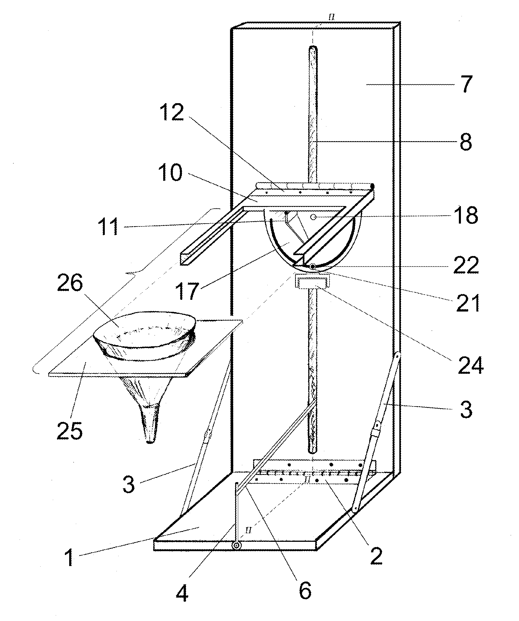
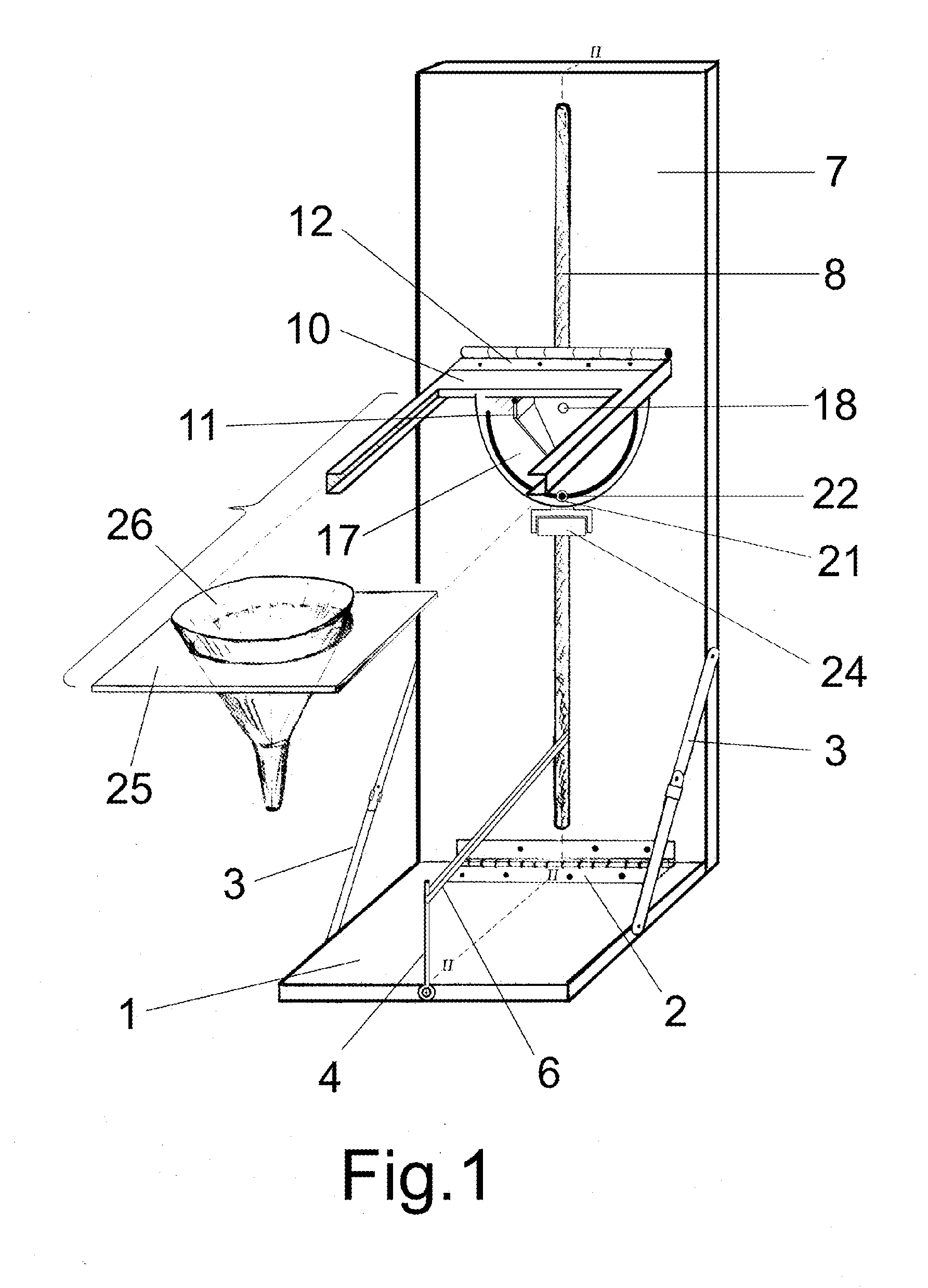
[0014]The base, the holder and the holder brace fold parallel with the vertical carrier for compact storage. The user opens the base to a right angle with the carrier and locks it in place with a sliding collar on the side hinged base braces. A funnel works best when held in a generally vertical orientation along the axis of the spout, so the sliding vertical adjustment assembly and object holder in this embodiment are configured to maintain a funnel support plate in a generally horizontal orientation.
[0016]The user selects a funnel with dimensions that allow the funnel spout to project into the receiving container opening without creating a seal around the opening, and then chooses a funnel support plate with a circular cutout diameter that best fits the upper portion of the funnel while allowing most of the funnel body to hang below the support plate. The support plate slides into a notched frame in the holder. If the base of the receiving container is so wide that it contacts the vertical carrier, the funnel support plate can hang a distance off the front end of the holder to reach the container opening and still adequately support the funnel. Using a set of support plates made of a stiff transparent material and placing the vertical adjustment handle on the back side of the vertical carrier minimizes visual obstruction of the funnel spout and the receiving container opening during vertical adjustment and the process of material transfer.
[0018]If the funnel spout projects a sufficient distance into the container opening to limit lateral movement by the top of the receiving container it will decrease the likelihood of tipping the container over. In many cases that alone will provide sufficient stability for the receiving container. If the only available funnel is a poor fit with the receiving container opening or if a container is to be left inverted in the funnel to drain for a long period where the stand might get jostled, it may be desirable to stabilize the base of the container as well.
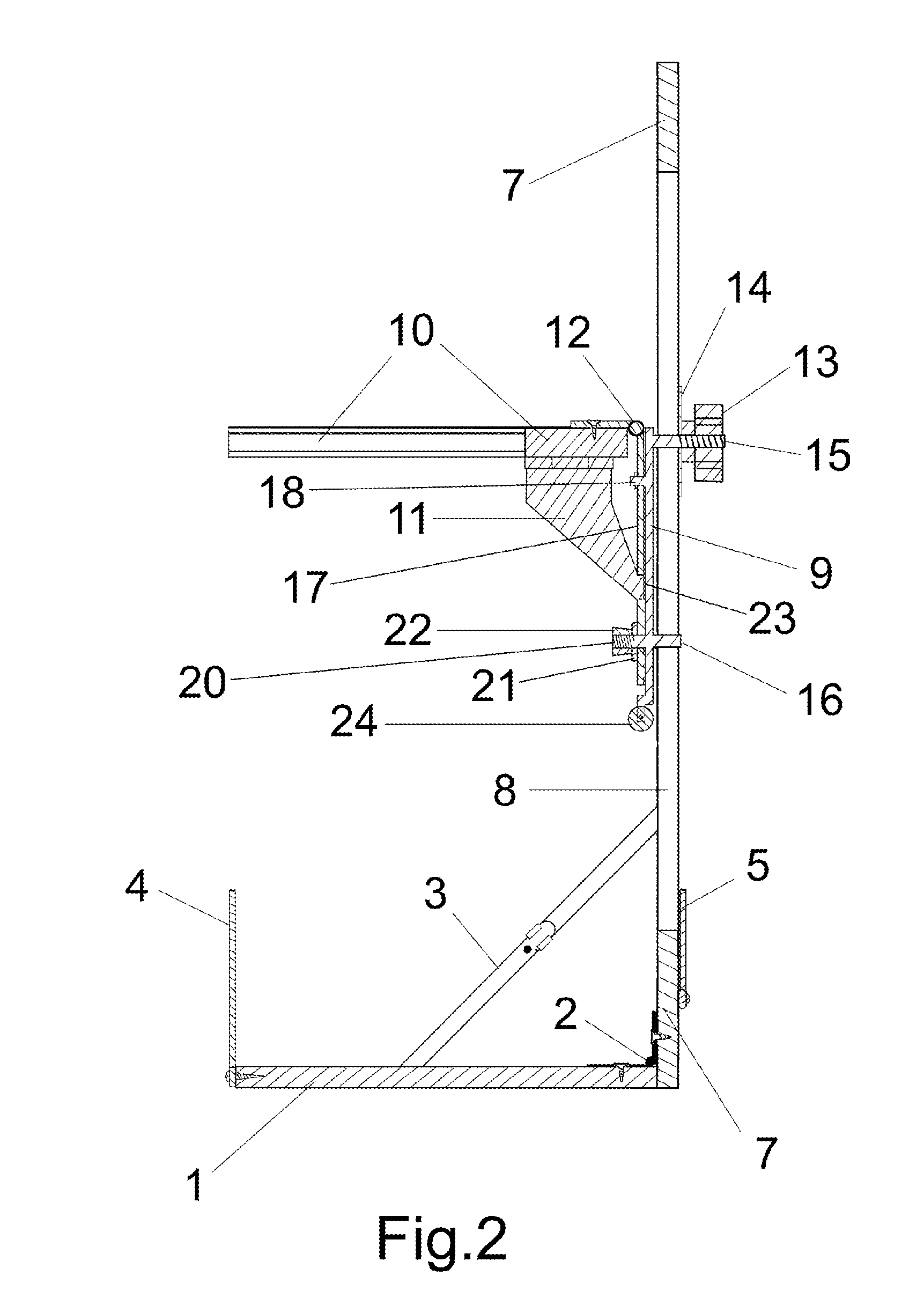
[0020]The choice of materials and surface textures used to construct a collapsible adjusting utility stand and the desired application will inform embodiments of the vertical carrier and vertical adjusting assembly that contribute to ease of operation. A vertical carrier with one or more vertical slots as the sole support and guide allows embodiments of the vertical adjusting assembly that eliminate much of the bulk, weight, and frictional resistance found in sliding or telescoping arms. Movement from side to side and rotation in the plane of the vertical carrier can be limited by four relatively small contact sites; in the embodiment described herein by the either side of two shafts contacting the edges of a single slot. Movement from front to back and rotational movement by the vertical adjusting assembly in the described embodiment can be limited by interactions between relatively small surfaces acting against both faces of the vertical carrier adjacent to the slot. The latter function could also be accomplished through minimal surface contact with grooves placed along the edges of the slot or slots.
[0021]Wheels or rollers may be employed where frictional resistance to movement would be otherwise unacceptable. The embodiment of the vertical adjustment assembly illustrated herein for the funnel holder configuration employs a bottom roller that sits approximately flush with the back side of the back plate. As the adjustment handle is loosened from the back side of the vertical carrier, the weight of the holder will tend to tip the adjustment assembly forward at the top and bring the roller in contact with the face of the vertical carrier. Wheels or rollers might also be spring loaded to assist in holding surfaces of moving parts away from fixed surfaces while the vertical adjustment assembly is moving.

Problems solved by technology

One person trying to use an ordinary funnel encounters an equally familiar set of problems, particularly if the receiving container is lightweight and tall with a narrow base, and the fluid in transfer is viscous.
The stack, including the funnel and receiving container, becomes top heavy and prone to tipping.
Downward pressure on the funnel spout tends to exacerbate the problem by sealing the spout against the edge of the container opening, preventing the escape of displaced air.
Material can quickly build up in the funnel and spill over the edge or tip the stack.
Vertically adjusting funnel holders that extend the vertical supporting member using tubes or sliding arms are not conducive to operation using only one hand due in part to frictional resistance between the relatively large surface areas in contact between fixed and moving parts.
Sliding arms and telescoping tubes add weight to the moving parts and deny access of the funnel holder to a good portion of the vertical range spanned by the vertical support member as a whole.
Approaches that employ sliding collars that ride on fixed length posts can avoid some of these problems but are still prone to binding and fouling, can be difficult to clean, and generally require two hands for changing and fixing elevation.
If the funnel spout projects a sufficient distance into the container opening to limit lateral movement by the top of the receiving container it will decrease the likelihood of tipping the container over.
Wheels or rollers may be employed where frictional resistance to movement would be otherwise unacceptable.

Method used


Image

  • Collapsible Adjusting Funnel Stand
  • Collapsible Adjusting Funnel Stand
  • Collapsible Adjusting Funnel Stand

Examples


Embodiment Construction

[0031]The present invention will now be described with reference to the accompanying figures. For purposes of the description hereinafter, the terms “right”, “left”, “top”, “side,”“front”, “back” and derivatives thereof shall relate to the invention as it is oriented in the drawing figures. However, it is to be understood that the invention may assume various alternative variations, except where expressly specified to the contrary. It is to be understood that the specific apparatus illustrated in the attached figures and described in the following specification is simply an exemplary embodiment of the present invention. Hence, specific dimensions and other physical characteristics related to the embodiments disclosed herein are not to be considered as limiting.

[0032]FIG. 1 depicts an embodiment of a collapsible adjusting utility stand configured as a funnel stand, including a platform base 1 attached to a vertical carrier 7 with a base hinge 2. Traveling vertically along a guide slo...


PUM


Abstract

A collapsible adjusting utility stand that folds flat for convenient storage and deploys quickly. The stand can be used to stabilize one object over a base surface and hold a second object in a desired orientation relative to the base while adjusting and fixing the vertical elevation of the second object. We describe in detail an embodiment configured as a collapsible adjusting funnel stand.

Description

CROSS-REFERENCE TO RELATED APPLICATIONS[0001]The present application claims the priority date of a prior filed provisional patent application No. 61 / 406,147 and an official filing date of Oct. 24, 2010 and which discloses substantially similar matter as described herein.STATEMENT REGARDING FEDERALLY SPONSORED RESEARCH OR DEVELOPMENT[0002]Not ApplicableREFERENCE TO SEQUENCE LISTING, A TABLE, OR A COMPUTER PROGRAM LISTING COMPACT DISC APPENDIX[0003]Not ApplicableBACKGROUND OF THE INVENTION[0004]Instances arise where it is desirable to hold an object fixed in orientation relative to another object while adjusting the distance between them vertically. When the task requires more than two hands or the relative orientation must be maintained over a long period, a device to assist in performing these functions would prove useful. One embodiment of such an aid configured to hold funnels of varying dimensions in an approximately vertical orientation over receiving containers of varying dimen...

Claims


Application Information

Patent Timeline
IPC IPC(8): F16M11/38
CPCB67C11/00
Inventor CARLSON, BARBARA ROSE
Owner CARLSON BARBARA ROSE
Learn More