Derail assembly
a technology of derails and assembly parts, applied in the direction of rail engagement elements, interlocking arrangments of points, transportation and packaging, etc., can solve the problems of ineffective derails, unsafe use of existing derails higher than three inches above the rail, and serious injury or death of workers in the area
- Summary
- Abstract
- Description
- Claims
- Application Information
AI Technical Summary
Benefits of technology
Problems solved by technology
Method used
Image
Examples
Embodiment Construction
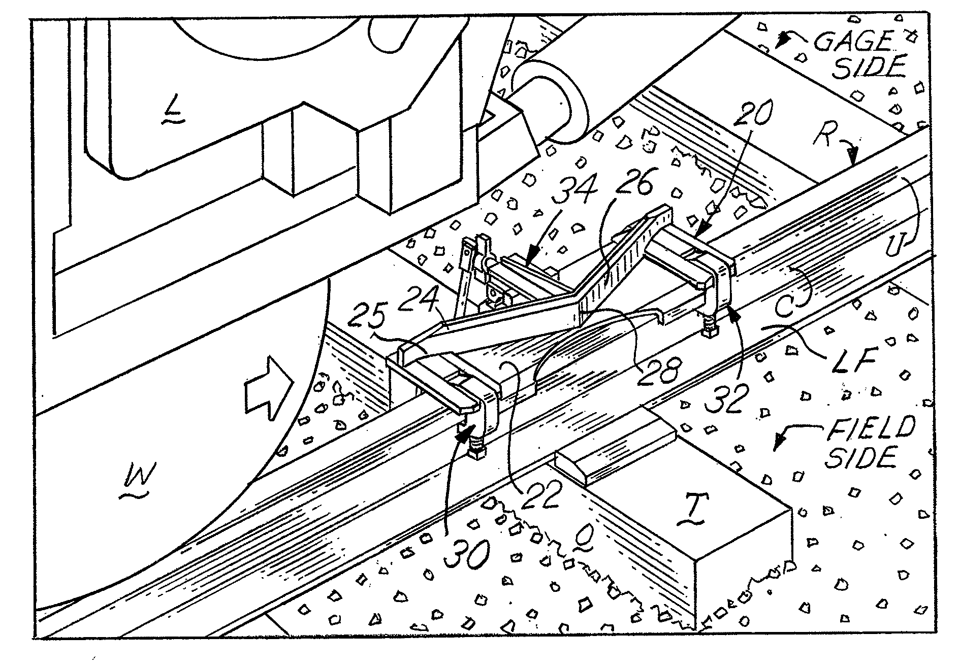
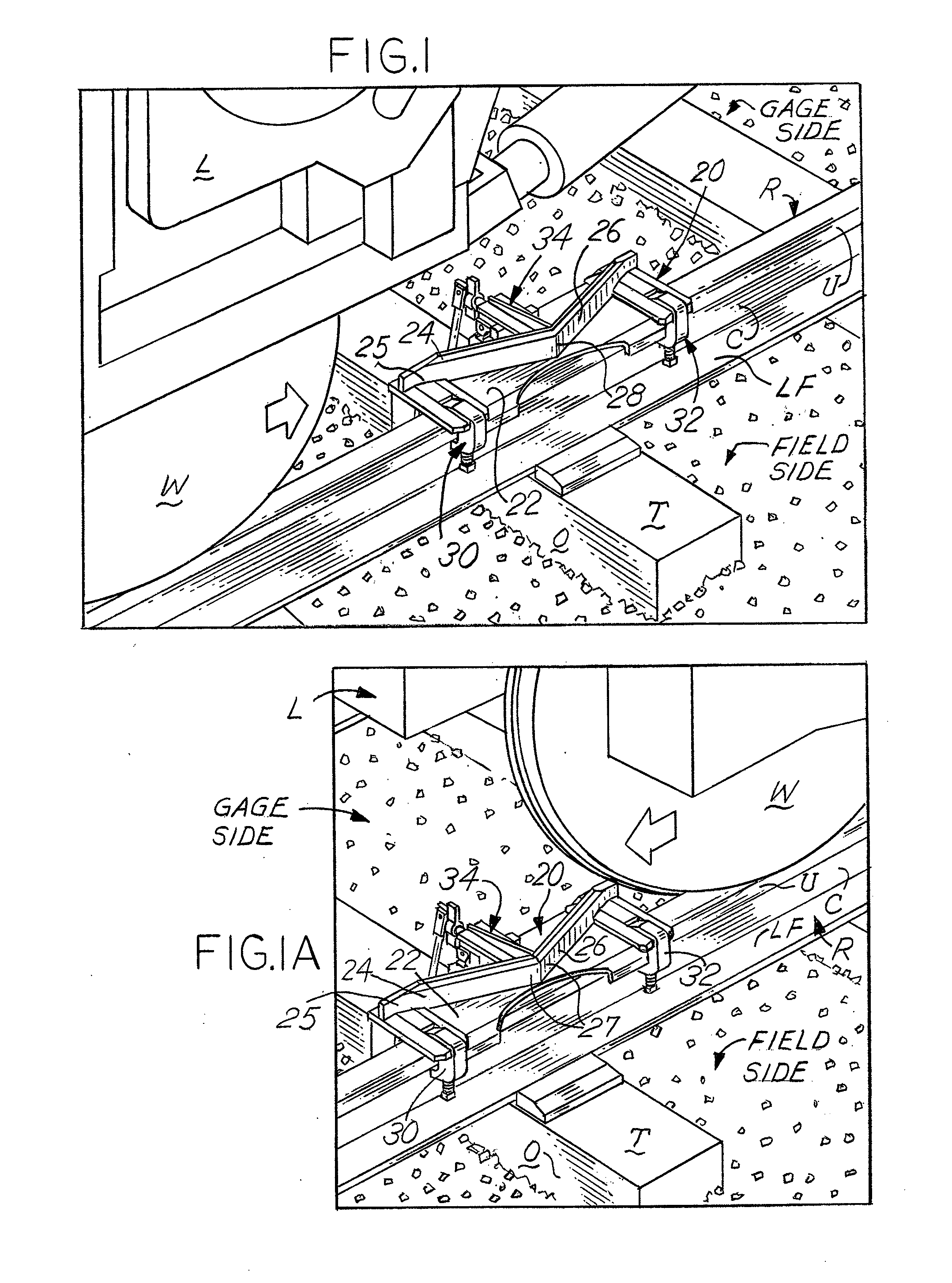
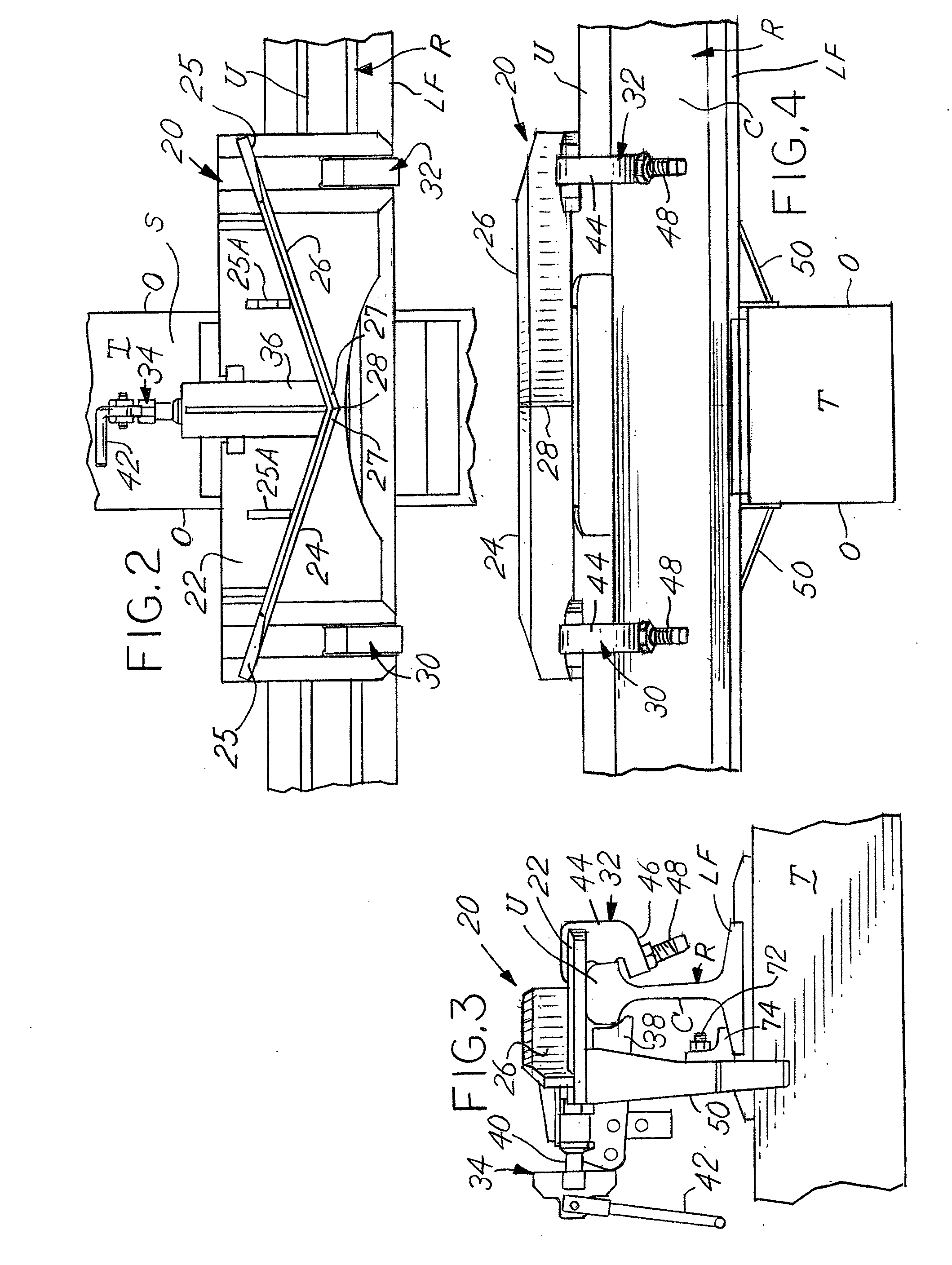
[0030]Referring to FIGS. 1 and 1A of the drawings, the manner of using the double ended derail assembly, generally 20, is shown. The front of a locomotive L is shown as it moves along a pair of conventionally spaced longitudinal steel railroad track rails R which are fixedly supported in the usual manner upon transverse railroad ties T. The ties T are mounted transverse to the spaced elongated rails (only one rail R being shown in the drawings) upon which a locomotive L is moving. The front lower portion of the locomotive is provided with a pilot (not shown). Further details of the locomotive L and the pilot are shown in U.S. Publication No. 2010 / 0051757 which is incorporated herein by reference. Relatively new railroad industry specifications allow the lowest point of a pilot to have a clearance of only three inches above the top surface of the rail R. If the locomotive L is moving undesirably, usually at low speeds such as five miles per hour, and possibly above that, the derail a...
PUM
 Abstract
Description
Claims
Application Information
 - R&D
- Intellectual Property
- Life Sciences
- Materials
- Tech Scout
- Unparalleled Data Quality
- Higher Quality Content
- 60% Fewer Hallucinations
Browse by: Latest US Patents, China's latest patents, Technical Efficacy Thesaurus, Application Domain, Technology Topic, Popular Technical Reports.
© 2025 PatSnap. All rights reserved.Legal|Privacy policy|Modern Slavery Act Transparency Statement|Sitemap|About US| Contact US: help@patsnap.com


