
Method and apparatus for machine coordination which maintains line-of-site contact

a technology of line-of-site contact and machine coordination, which is applied in the direction of vehicle position/course/altitude control, process and machine control, instruments, etc., can solve the problems of inability to allow, equipment may be completely different, and the margin of error in operation is not allowed, so as to facilitate the operation of autonomous equipment, adequate safeguarding, and adequate positioning accuracy

Inactive Publication Date: 2012-04-19
DEERE & CO
View PDF3 Cites 86 Cited by
  • Summary
  • Abstract
  • Description
  • Claims
  • Application Information

AI Technical Summary

Benefits of technology

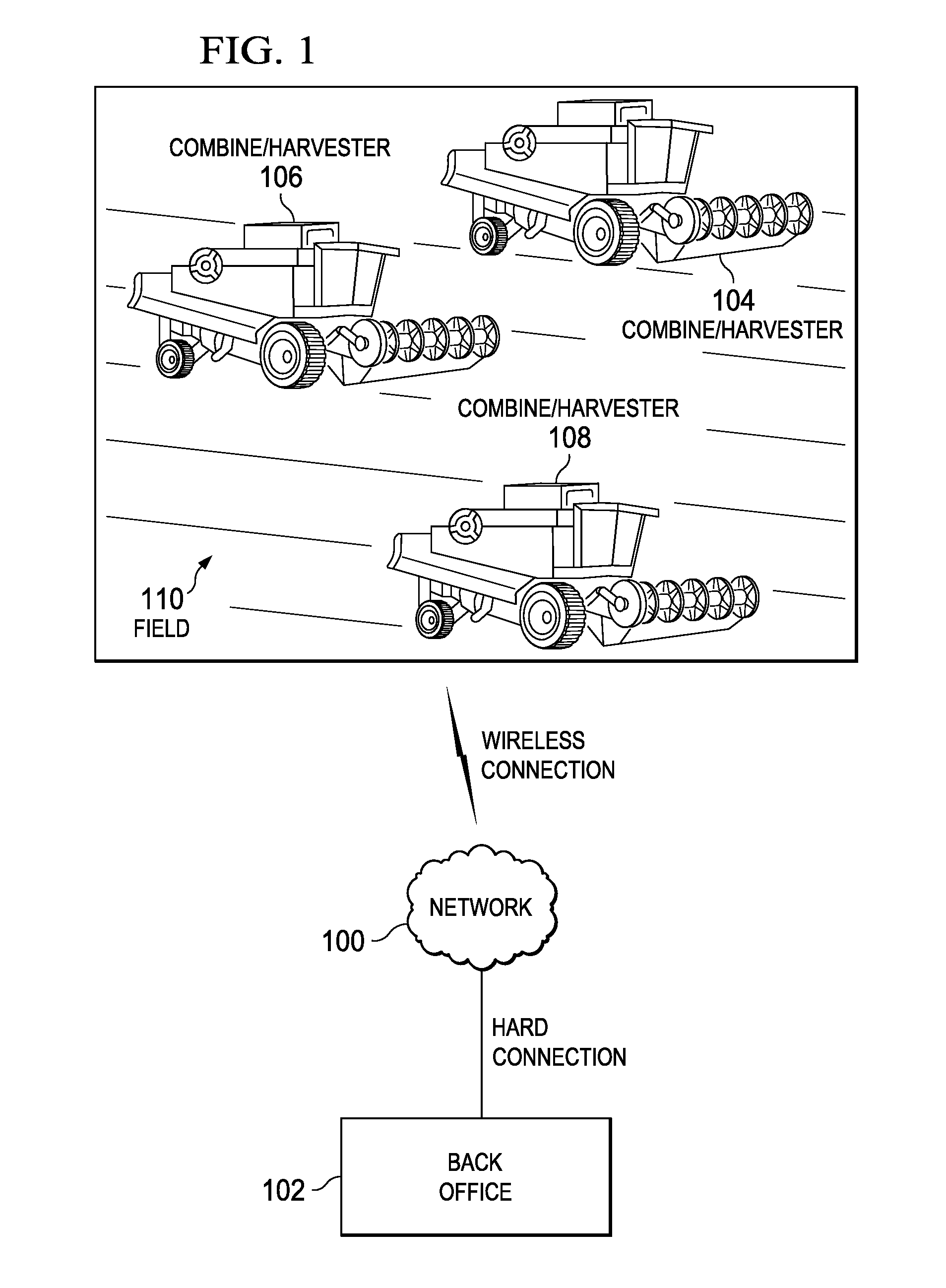
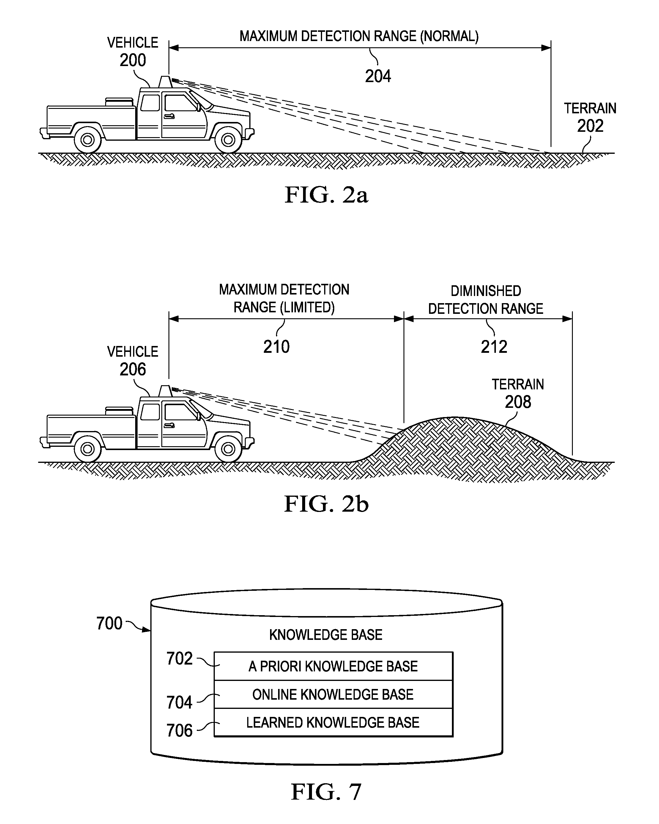
[0005]A method and system are provided that facilitates operation of autonomous equipment by providing a mission planner to maintain line-of-sight contact between a plurality of coordinated machines. The mission planner may be used when coordination needs machines to remain within a specified distance of each other to provide adequate ‘positioning’ accuracy, or else to provide adequate safeguarding. It may also be needed when communication or sensing signals may be blocked by earth, buildings, vegetation, and other features on a worksite. Providing such line-of-sight contact between a plurality of coordinated machines advantageously allows for the possibility of using a plurality of different mechanisms (e.g., GPS, imaging, LIDAR) that allow for recovery from a plurality of different types of errors that may be encountered.

Problems solved by technology

In some situations with the trend, this equipment may be completely different from the operator controlled equipment that may be replaced, and does not allow for any situations in which an operator can be present or take over operation of the vehicle.
However, in such environments, the margin of error in operation—be it from a malfunctioning part, environmental issues, or the terrain of the work environment—may be extremely small as the machines operate autonomously without operator control.

Method used


Image

  • Method and apparatus for machine coordination which maintains line-of-site contact
  • Method and apparatus for machine coordination which maintains line-of-site contact
  • Method and apparatus for machine coordination which maintains line-of-site contact

Examples


Embodiment Construction

[0022]Embodiments provide systems and methods for vehicle navigation and more particularly systems and methods for a distributed knowledge base within a vehicle for controlling operation of a vehicle. As an example, embodiments provide a method and system for utilizing a versatile robotic control module for localization and navigation of a vehicle.

[0023]Robotic or autonomous vehicles, sometimes referred to as mobile robotic platforms, generally have a robotic control system that controls the operational systems of the vehicle. In a vehicle that may be limited to a transportation function, the operational systems may include steering, braking, transmission, and throttle systems. Such autonomous vehicles generally have a centralized robotic control system for control of the operational systems of the vehicle. Some military vehicles have been adapted for autonomous operation. In the United States, some tanks, personnel carriers, Stryker vehicles, and other vehicles have been adapted fo...


PUM


Abstract

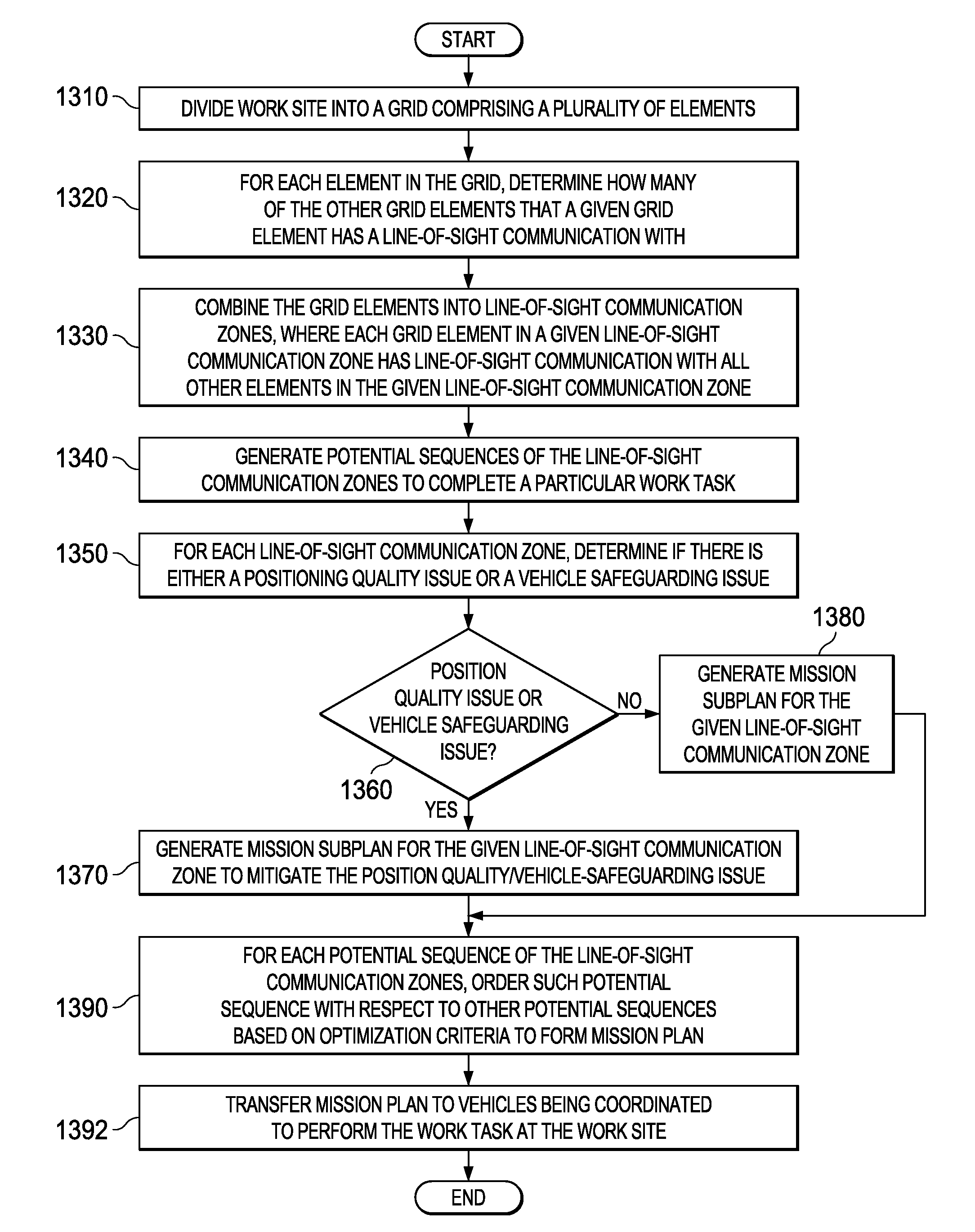
A method and system that facilitates operation of autonomous equipment by providing a mission planner to maintain line-of-sight contact between a plurality of coordinated machines, including a method for maintaining line-of-sight (LoS) communication between a plurality of machines that creates a mission plan for a work site that includes a path plan for each of the plurality of machines that maintains the line-of-sight communication between the plurality of machines by taking into account a topography for the work site; and loads the path plan for each respective one of the plurality of machines into each respective one of the plurality of machines, wherein the path plan specifies a machine travel path for each respective one of the plurality of machines.

Description

CROSS REFERENCE TO RELATED APPLICATIONS[0001]This application is related to commonly assigned and co-pending U.S. patent application Ser. No. 12 / 208,691 entitled “HIGH INTEGRITY PERCEPTION FOR MACHINE LOCALIZATION AND SAFEGUARDING”, which is hereby incorporated by reference.FIELD OF THE INVENTION[0002]The preferred embodiment relates generally to coordinating a plurality of vehicle operations that are operable to perform a task, and in particular may be directed to maintaining a line-of-site communication between such plurality of vehicles to provide a fail-safe recovery mechanism due to a failure or other operating / environmental issue.BACKGROUND OF THE INVENTION[0003]An increasing trend towards developing automated or semi-automated equipment may be present in today's work environment. In some situations with the trend, this equipment may be completely different from the operator controlled equipment that may be replaced, and does not allow for any situations in which an operator c...

Claims


Application Information

Patent Timeline
Patent Type & Authority Applications(United States)
IPC IPC(8): G06F19/00
CPCB60W2300/158G05D1/024G05D1/0246G05D2201/0201G05D1/0274G05D1/0278G05D1/0297G05D1/0257G05D1/0231G05D1/0242G05D1/028G05D1/0291
Inventor ANDERSON, NOEL WAYNE
Owner DEERE & CO
Learn More