
Zoom lens and imaging apparatus incorporating the same

a technology of zoom lens and imaging apparatus, applied in the field of zoom lens, can solve the problems of unnatural images and fast operation of functions, and achieve the effects of easy zooming sharing, high zoom ratio, and high zoom ratio

Active Publication Date: 2012-04-19
OM DIGITAL SOLUTIONS CORP
View PDF4 Cites 80 Cited by
  • Summary
  • Abstract
  • Description
  • Claims
  • Application Information

AI Technical Summary

Benefits of technology

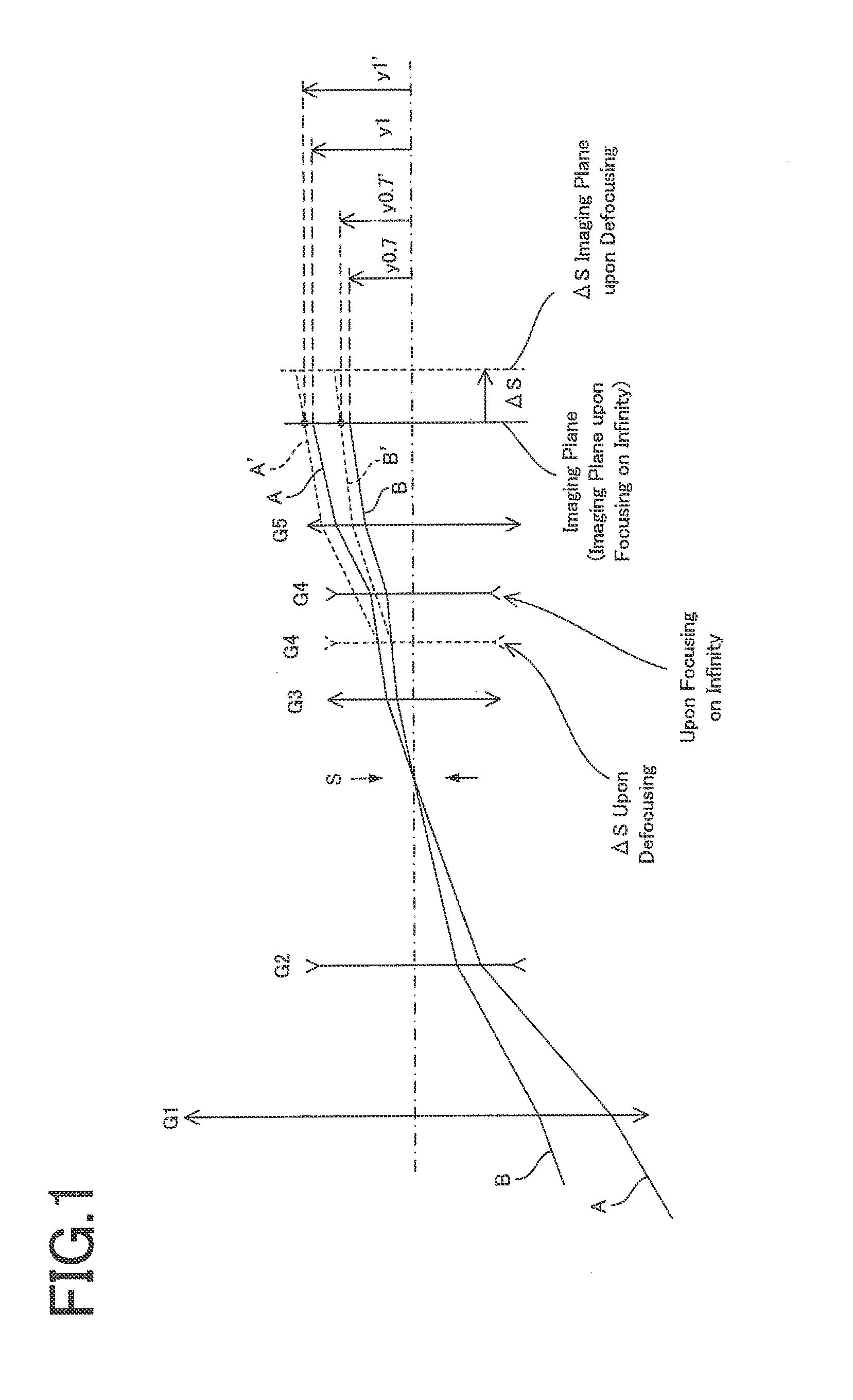
[0024]The adoption of the positive-power leadoff type zoom lens wherein the lens group of positive refracting power is located on the most object side works for making sure high zoom ratios, and provides a lens layout preferable for a wide-angle, high-zooming zoom lens. A separation change between the first and the second lens group and a separation change between the second and the third lens group take a substantial part in zooming so that image position adjustment or the like is implemented by a separation change between the subsequent lens groups. In addition, the provision of the fourth lens group of negative refracting power and the fifth lens group of positive refracting power enables the exit pupil to be properly positioned to make the size of the first or the fourth lens group small. It is thus possible to set up a small-format, less costly zoom lens.
[0157]Of Condition (2B), the upper limit value is set at preferably 14.1. More preferably, there should be a lower limit value of not less than 8.0 provided or the purpose of helping make sure the refracting power necessary for each lens, which works for making sure high zoom ratios.

Problems solved by technology

This wobbling function requires very fast operation depending on frame rates; so there is still mounting demand for reducing the weight of a lens used for wobbling.
In other words, it is controlled such that any out-of-focus state during wobbling cannot be recognized; however, when there is a large image magnification change (changes in the size of a subject on the imaging plane), images look quite unnatural because they look as if they were always waving.

Method used


Image

  • Zoom lens and imaging apparatus incorporating the same
  • Zoom lens and imaging apparatus incorporating the same
  • Zoom lens and imaging apparatus incorporating the same

Examples


example 1

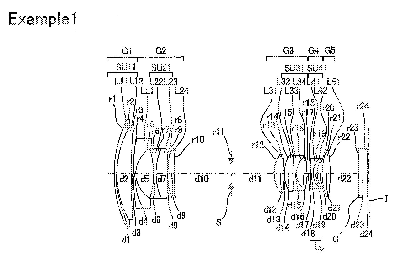
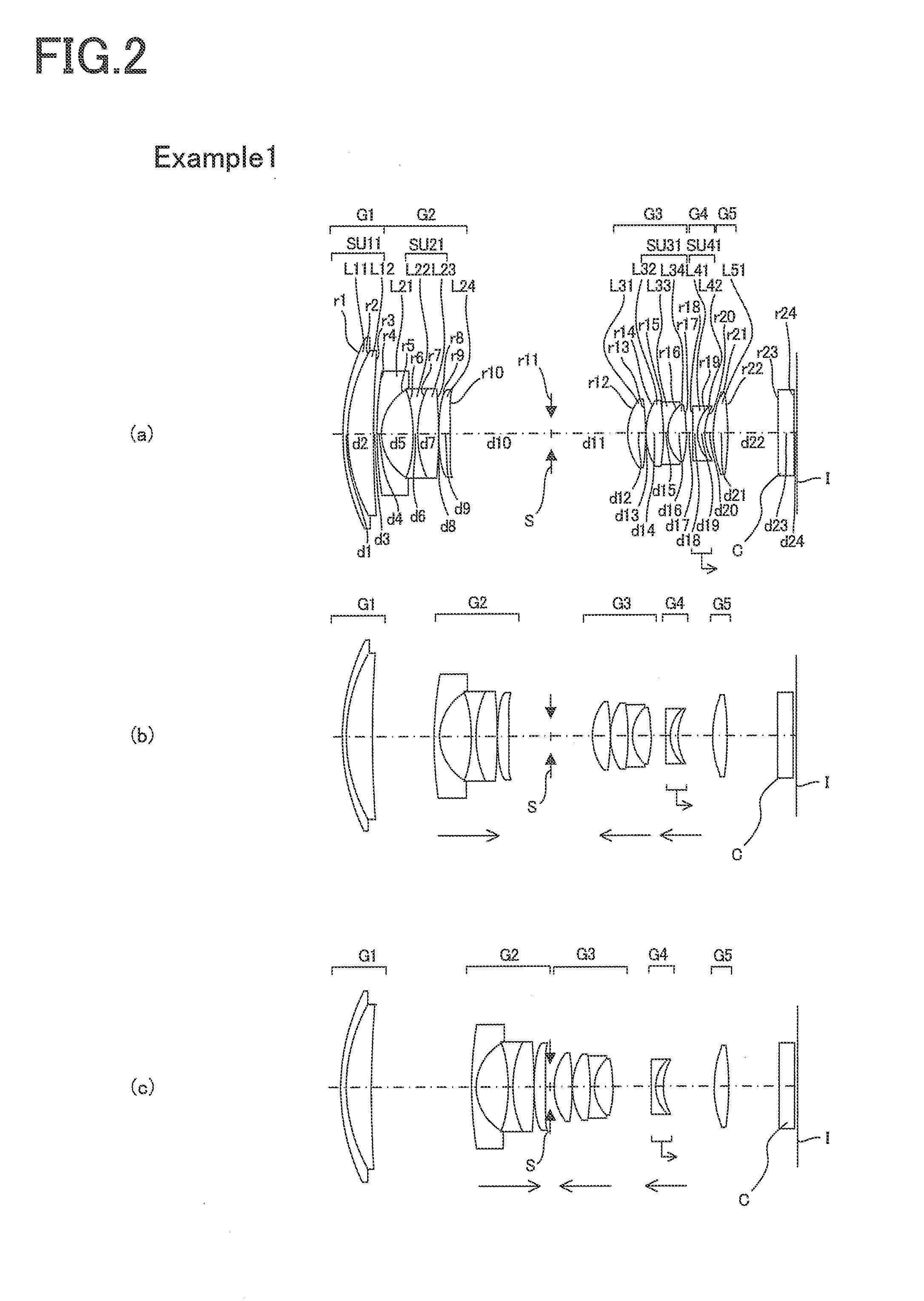
Numeral Example 1

[0286]

Surface No.rdndνd 156.9121.401.8466623.78 245.1476.691.7291654.68 3283.392D3 (variable) 4111.6251.201.8348142.71 513.6028.52 6−34.0831.101.7880047.37 728.7055.461.8466623.78 8−132.0780.10 9 (Aspheric Surface)82.3202.981.5254255.7810 (Aspheric Surface)−127.407D10 (variable)11 (Stop)∞D11 (variable)12 (Aspheric Surface)14.7824.641.4970081.5413 (Aspheric Surface)−58.8890.101416.1904.521.5163364.1415−71.7301.351.8830040.761610.3344.771.4970081.5417 (Aspheric Surface)−26.510D17 (variable)18−589.5511.001.8040046.57199.4382.061.8466623.782013.756D20 (variable)21 (Aspheric Surface)30.3563.901.5163364.1422 (Aspheric Surface)−70.71413.40 23∞4.001.5163364.1424∞0.8 Image Plane∞Aspheric Data9th SurfaceK = 0.000, A4 = 4.81480E−05, A6 = −9.50101E−08, A8 = 3.10123E−09,A10 = −1.06248E−1110th SurfaceK = 0.000, A4 = 3.17860E−05, A6 = −5.95034E−08, A8 = 3.20925E−09,A10 = −1.28394E−1112th SurfaceK = 0.000, A4 = −2.14397E−05, A6 = 3.59448E−07,A8 = −7.60025E−09, A10 = 5.16822E−1113th...

example 2

Numeral Example 2

[0287]

Surface No.rdndνd 196.8111.401.8466623.78 269.4224.111.7291654.68 3222.2220.10 473.3123.451.7291654.68 5191.343D5 (variable) 6113.1251.201.8160046.62 713.9218.22 8−28.3741.101.7291654.68 928.3824.921.8051825.4610−135.9110.1011 (Aspheric Surface)144.6472.651.5254255.7812 (Aspheric Surface)−87.751D12 (variable)13 (Stop)∞D13 (variable)14 (Aspheric Surface)14.2085.571.4970081.5415 (Aspheric Surface)−42.7240.101618.6123.771.5163364.1417−40.1041.301.8830040.761811.8794.991.4970081.5419 (Aspheric Surface)−21.633D19 (variable)20−1106.0451.001.8040046.57218.7982.331.8466623.782212.922D22 (variable)23 (Aspheric Surface)33.8453.911.5163364.1424 (Aspheric Surface)−64.91113.56 25∞4.001.5163364.1426∞0.80Image Plane∞Aspheric Data11th SurfaceK = 0.000, A4 = 3.49846E−05, A6 = −3.03078E−07, A8 = 3.21587E−09,A10 = −7.90949E−1212th SurfaceK = 0.000, A4 = 2.13323E−05, A6 = −2.67929E−07, A8 = 3.30300E−09,A10 = −8.69171E−1214th SurfaceK = 0.000, A4 = −2.54966E−05, A6 = 3.51889E−07,A...

example 3

Numeral Example 3

[0288]

Surface No.rdndνd 1146.5442.001.8466623.78 276.0415.461.7291654.68 3512.8550.20 440.0285.441.7291654.68 597.078D5 (variable) 694.4071.001.8348142.71 7 (Aspheric Surface)12.2448.11 8−22.3551.001.8040046.57 937.3600.001037.3864.321.8466623.7811−46.1640.2512 (Aspheric Surface)−53.3733.071.5254255.7813 (Aspheric Surface)−30.818D13 (variable)14 (Stop)∞D14 (variable)15 (Aspheric Surface)20.1134.671.4970081.5416 (Aspheric Surface)−59.1540.211714.5086.371.4874970.2318−34.4351.001.8040046.5719 (Aspheric Surface)345.9530.202084.1430.801.8010034.972110.6184.511.4970081.5422 (Aspheric Surface)−47.543D22 (variable)234726.9441.001.8830040.76249.4283.211.8466623.782517.732D25 (variable)26 (Aspheric Surface)28.6205.301.5163364.1427 (Aspheric Surface)−80.85111.6028∞4.001.5163364.1429∞0.80Image Plane∞Aspheric Data 7th SurfaceK = −0.209, A4 = 1.28579E−05, A6 = 6.33708E−08, A8 = 9.42400E−10, A10 = −4.73717E−1312th SurfaceK = 0.000, A4 = −4.46566E−06, A6 = 1.16292E−07, A8 = −6.995...


PUM


Abstract

A zoom lens comprising, in order from an object side thereof, a first lens group of positive refracting power, a second lens group of negative refracting power, an aperture stop, a third lens group of positive refracting power, a fourth lens group of negative refracting power, and a fifth lens group of positive refracting power. Upon zooming from the wide-angle end to the telephoto end, at least the first lens group and the aperture stop remain fixed in position, the second and third lens groups move in the optical axis direction, and the separation between each of the lens groups and the aperture stop changes. Upon focusing from a focusing-on-infinity state to a close-range-focusing state, the fourth lens group moves in the optical axis direction, with satisfaction of the following:−0.36<f4 / f1<−0.05  (1A),where f1 and f4 are the focal lengths of the first and fourth lens groups, respectively.

Description

[0001]This application claims benefit of Japanese Application No. 2010-230639 filed in Japan on Oct. 13, 2010 and No. 2010-230640 filed in Japan on Oct. 13, 2010, the contents of which are incorporated by this reference.BACKGROUND OF THE INVENTION[0002]The present invention relates to a zoom lens that has its full length remaining constant during zooming, and focusing. Specifically, the invention relates to a small-format, wide-angle, high-zooming zoom lens that is well fit for an interchangeable lens system and capable of taking moving images. More specifically, the invention relates to an imaging apparatus equipped with a zoom lens having its full length remaining constant during zooming, and focusing.[0003]So far, some digital camera products have been known to be capable of taking moving images. In recent years, interchangeable type digital cameras, inter alia, an interchangeable lens compatible with the function of the camera body of taking moving images have also been under st...

Claims


Application Information

Patent Timeline
Patent Type & Authority Applications(United States)
IPC IPC(8): G02B15/14
CPCG02B15/173G02B15/145121
Inventor TOCHIGI, AKIYOSHIKAWAMURA, KAZUTERUYAMADA, YASUHARU
Owner OM DIGITAL SOLUTIONS CORP
Learn More