Device for locking second leaves in the closed configuration
a technology of closed configuration and second leaves, which is applied in the direction of mechanical controls, door/window fittings, fastening means, etc., can solve the problems of general difficulty in gripping, degrading the manoeuvrability of the free end of the lever, and affecting the manoeuvrability of the lever
- Summary
- Abstract
- Description
- Claims
- Application Information
AI Technical Summary
Benefits of technology
Problems solved by technology
Method used
Image

Examples
first embodiment
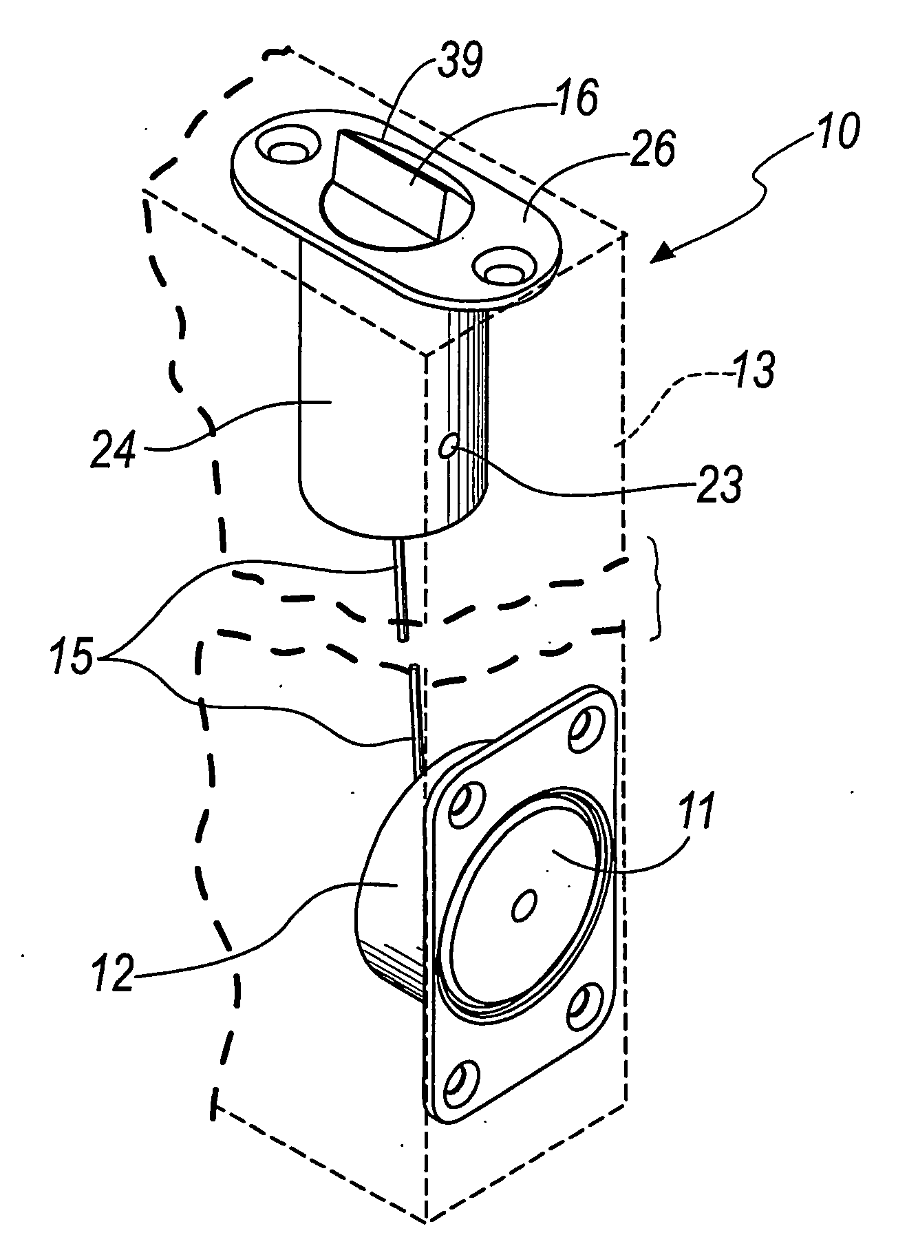
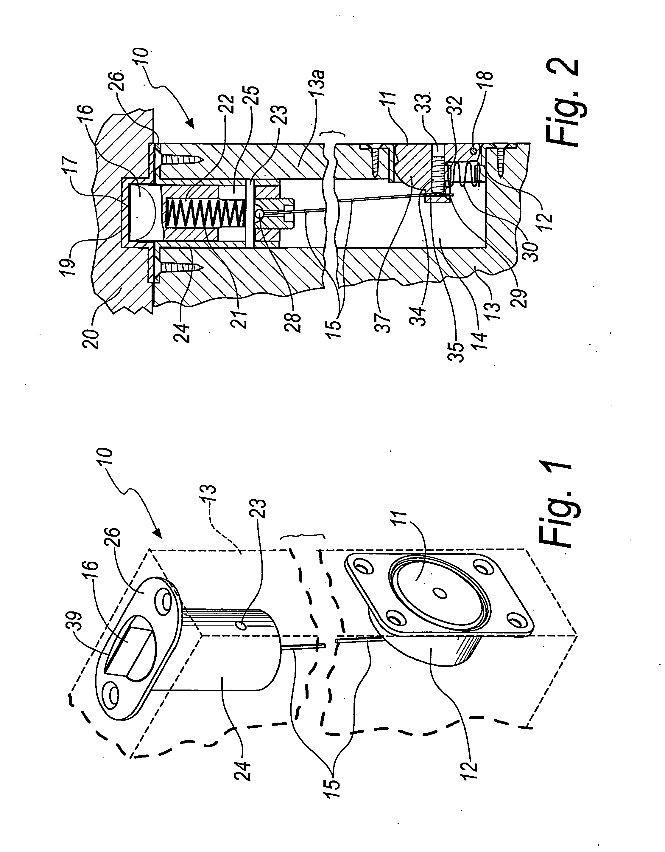
[0034]With reference to the figures, a device for locking second leaves in the closed configuration, according to the invention, is generally designated, in its first embodiment shown in FIGS. 1 to 3, by the reference numeral 10.
[0035]The device 10 comprises a recessed button 11 which is pivoted to a corresponding accommodation body 12.
[0036]The accommodation body 12 is recessed in a second leaf 13, in a corresponding seat 14 formed in the second leaf 13.
[0037]The button 11, which is pivoted to the accommodation body 12 by means of the pivot 18, is designed to be pushed, by the manual action of a user, towards the inside of the body 12 and therefore of the leaf 13 itself.
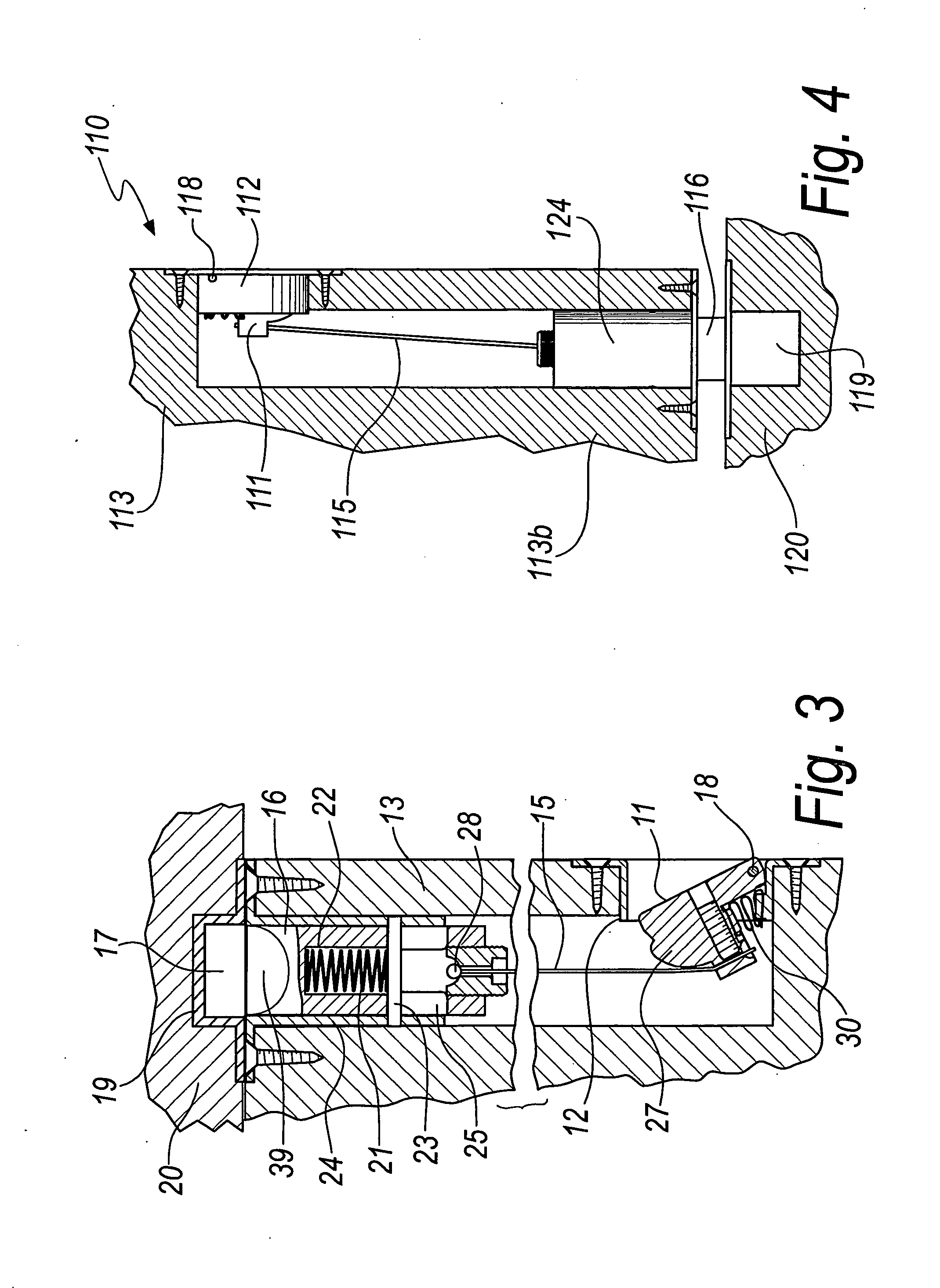
[0038]The rotation of the button 11 produces, by means of a transmission element 15, the retraction towards the inside of the leaf 13 of a latch 16, which is normally pushed vertically towards the architrave in engagement in a corresponding seat 17 to lock the leaf 13.
[0039]The seat 17 is formed on a plate 19 set in...
second embodiment
[0058]FIG. 4 shows the device according to the invention, indicated therein by the reference numeral 110.
[0059]Such second embodiment of the device 110 according to the invention is designed to be applied to the lower part 113b of a second leaf 113.
[0060]The device 110 presents, similarly to the first embodiment, a latch 116, a sleeve 124 which contains it, a mortise 119 to be recessed in the floor 120 forming a seat 117 for the latch 116, a button 111, an accommodation body 112, and a pivot 118 for the button 111, as well as a transmission element 115.
[0061]FIGS. 5 and 6 clearly show how the latch 116 has at its end a roller 140, designed to rest on the floor 120, allowing the gliding of the latch 116 upon it without sliding, thus protecting the integrity of the floor.
[0062]The operation of the device 110 is the same as of the device 10 in its first embodiment, with the difference that the button 111, once pressed, produces the lifting of the latch 116, while the helical spring ins...
third embodiment
[0063]FIGS. 7 and 8 show a device according to the invention in the same, in which the particularity of the button, indicated by the reference numeral 211, is highlighted.
[0064]The button 211 is designed to simultaneously control both an upper latch, like the latch 16 described for the first embodiment, and a lower latch, like the latch 116 described for the second embodiment of the device according to the invention.
[0065]The button 211 is thus articulated in two parts 211a and 211b, which are mutually pivoted by means of a first pivot 218a, and each part is pivoted to the accommodation body 212 by means of a second pivot 218b and 218c respectively.
[0066]One of the two second pivots, for example the second lower pivot 218c, is also free to perform a translational motion in corresponding slots 245 formed on the accommodation body 212.
[0067]There are two elastic elements, 230a and 230b respectively, for the return of the button 211, one for each of the two parts 211a and 211b of the b...
PUM
 Abstract
Description
Claims
Application Information
 - R&D
- Intellectual Property
- Life Sciences
- Materials
- Tech Scout
- Unparalleled Data Quality
- Higher Quality Content
- 60% Fewer Hallucinations
Browse by: Latest US Patents, China's latest patents, Technical Efficacy Thesaurus, Application Domain, Technology Topic, Popular Technical Reports.
© 2025 PatSnap. All rights reserved.Legal|Privacy policy|Modern Slavery Act Transparency Statement|Sitemap|About US| Contact US: help@patsnap.com