
Tamperproof case

a technology of tamperproof cases and plastic plates, which is applied in the field of tamperproof cases, can solve the problems of creating fake cases, counterfeiters breaking one of the plastic plates,

Inactive Publication Date: 2012-03-22
SICPA HLDG SA
View PDF6 Cites 16 Cited by
  • Summary
  • Abstract
  • Description
  • Claims
  • Application Information

AI Technical Summary

Benefits of technology

[0063]One advantage of the tamperproof case of the present invention in comparison cases of the prior art is based on the choice of the sheet member according to its thickness and its ability to be compatible with, e.g., an IR and / or UV reader and its compatibility with the use of very small amount of security element detected by the use of IR and / or UV reader. By using this a combination of sheet member plus, e.g., security ink it is nearly impossible for a counterfeiter to at the first glance determine the presence of an invisible security element. Accordingly, if the counterfeiter merely replaces the two sheet members after having broken them by new ones, the government and retailers will know that counterfeiting has taken place (because of the absence of invisible security elements on and / or inside the replacement sheet members).

Problems solved by technology

Since for the above and other reasons many cases containing an article of value are in circulation there is a high temptation for counterfeiters to replace an encased coin of precious metal or other article of value inside a case with a counterfeit article of value in a reproduced case that looks like the original case and to sell the encased counterfeit article to unsuspecting consumers.
A main drawback of this case is the possibility for a counterfeiter to break one of the plastic plates, to replace the original coin with a fake one and to use a new plate to recreate the original case which contains a fake coin in a case which looks like the original case.
A main drawback of this assembly is the possibility to reproduce in the transparent lower element the indelible graphic pattern which is in the form of decorative imprints and thereby create a fake case.

Method used

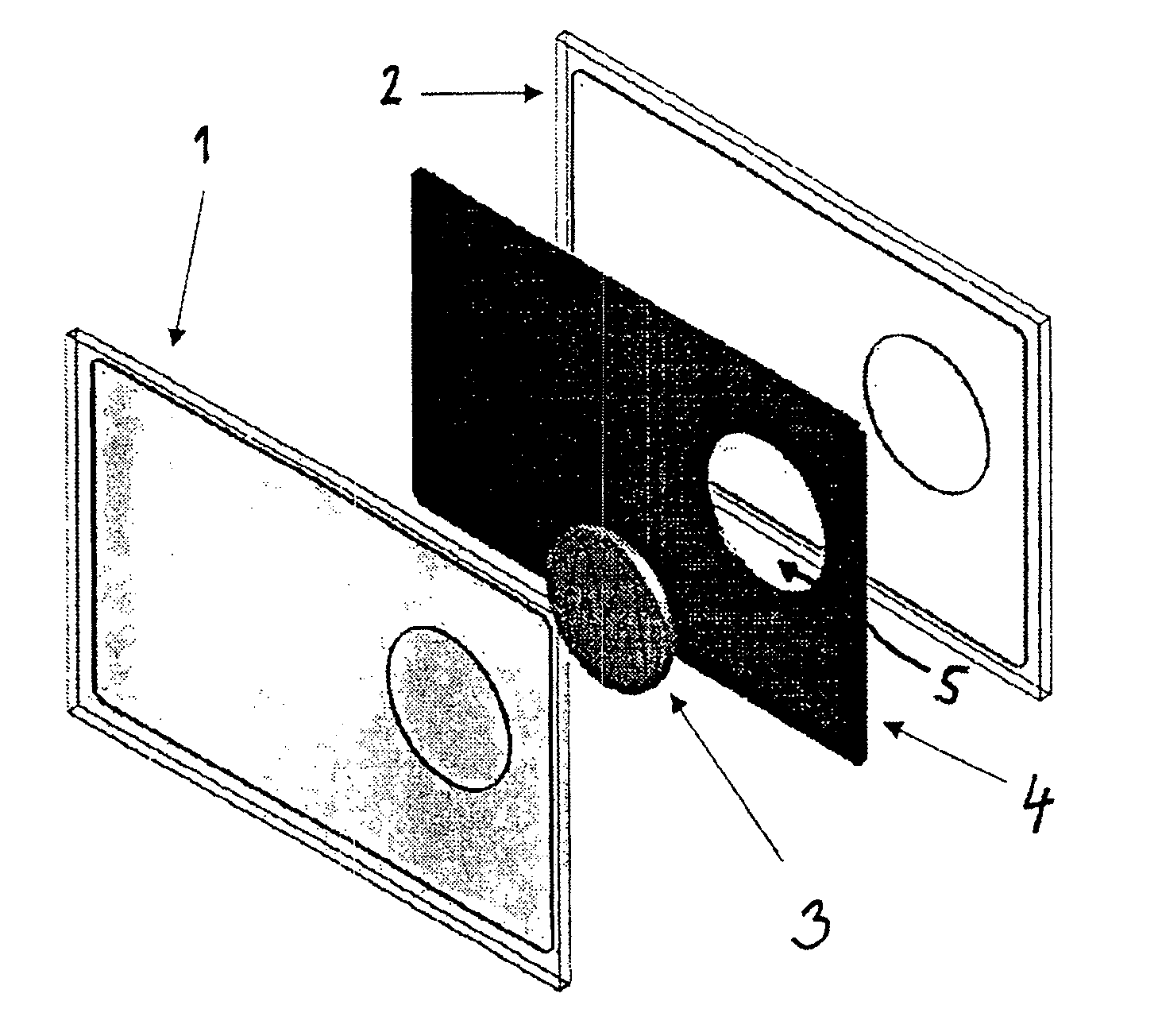
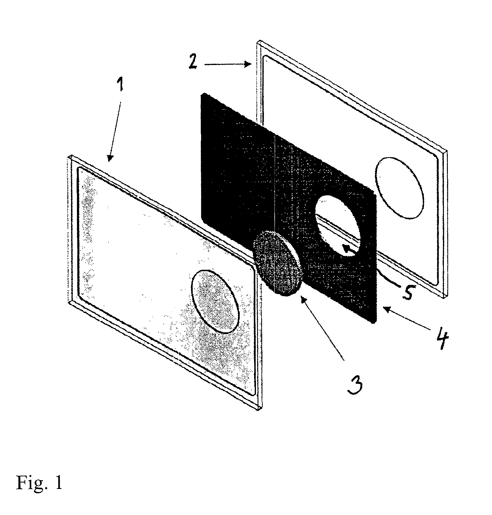
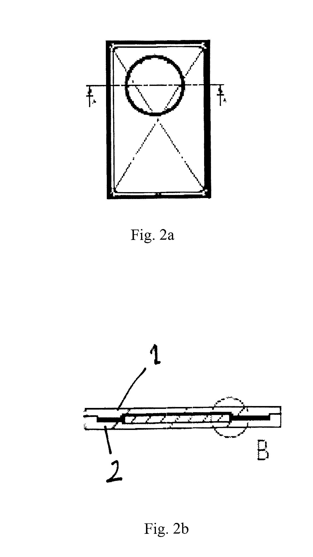

Image

  • Tamperproof case
  • Tamperproof case
  • Tamperproof case

Examples


example

[0064]A typical ink for ink jet printing for uses in the present invention is prepared as follows:

Black with Fluorescent Red (254 nm):

[0065]To a solution of deionized water (240 g) are added 2-pyrrolidone (30 g) and 1,2-hexanediol (15 g). The solution is stirred at 500-600 rpm in order to obtain a homogenized solution. 15 g of the complex Na3[Eu(dpa)3] (dpa=pyridine dicarboxylate) (or a larger complex such as Na5[Eu(dpa)5]) are added to the solution, then heated at 40° C. until the complex is completely dissolved. The resultant solution is cooled to ambient temperature, and the resultant mixture is stirred at 500-600 rpm for about 20 minutes. Thereafter, the solution is filtered to remove all insoluble materials and unreacted products.

[0066]The ink obtained by the above procedure is packaged in a HP45 cartridge and used with a Deskjet printer of the 960Cxi, 970Cxi, 980Cxi or 990 Cxi series. Fluorescence at 254 nm is detected using a Fisher Bioblock Scientific VL-4.LC lamp. Droplets ...


PUM

PropertyMeasurementUnit
Areaaaaaaaaaaa
Transparencyaaaaaaaaaa
Wavelengthaaaaaaaaaa

Abstract

A tamperproof case for a genuine article which comprises a space for accommodating the article between first and second sheet members which are capable of being permanently bonded together in at least the area that substantially completely surrounds the space. At least one of the first and second sheet members comprises at least one security element that is invisible under light in the visible wavelength range. This abstract is neither intended to define the invention disclosed in this specification nor intended to limit the scope of the invention in any way.

Description

CROSS-REFERENCE TO RELATED APPLICATIONS[0001]The present application claims the benefit under 35 U.S.C. §119(e) of U.S. Provisional Application No. 61 / 384,047, filed Sep. 17, 2010 and claims priority under 35 U.S.C. §119 of International Patent Application No. PCT / EP2010 / 063752, filed Sep. 17, 2010. The entire disclosures of these applications are expressly incorporated by reference herein.BACKGROUND OF THE INVENTION[0002]1. Field of the Invention[0003]The present invention relates to tamperproof case for a genuine article such as an article of value and in particular, a tamperproof case which comprises at least one security element. The present invention also relates to a method of making the tamperproof case and to a method of authenticating a genuine article by using the tamperproof case.[0004]2. Discussion of Background Information[0005]Many countries around the world have a National or Commemorative day. Often this day is an occasion for governments, public organizations or pri...

Claims


Application Information

Patent Timeline
IPC IPC(8): A45C1/00B65B5/02A45C11/00B65D71/00B42D15/00B65D90/02
CPCA45C1/10A45C13/18A47G1/12A45C2001/102A45C2001/104A45C13/185A47G1/06E05B73/00G09F3/0292G07D9/002A45C11/00
Inventor GREMAUD, FREDERICSCHWAB, XAVIERDECOUX, ERIC
Owner SICPA HLDG SA
Learn More