
Low-profile anterior vertebral plate assemblies and methods of use

a technology of anterior vertebral plates and low-profile, which is applied in the field of low-profile anterior vertebral plates, can solve the problems of affecting the fusion process, and requiring spinal fusion patients to suffer from severe pain, and the graft is associated with a relatively high rate of dislocation, and is not easily compressible. , the problem of low fusion ra

Active Publication Date: 2012-03-15
NEHLS DANIEL
View PDF7 Cites 18 Cited by
  • Summary
  • Abstract
  • Description
  • Claims
  • Application Information

AI Technical Summary

Benefits of technology

"The patent text describes a vertebral plate assembly that can be permanently implanted between superior and inferior vertebral bodies to treat spinal disorders. The assembly has a posterior surface that fits into the intervertebral space and an anterior surface that is external to the space. It includes a plurality of anchor members that are attached to the anterior surface and channels that align with the corners of the vertebral bodies to secure the assembly. The technical effect of this invention is to provide a reliable and effective method for spinal fusion that reduces the risk of complications and improves patient outcomes."

Problems solved by technology

Patients requiring spinal fusion typically suffer from either neurological deficits or severe pain which has not responded to conservative treatment.
Unfortunately, grafts are associated with a relatively high rate of dislodgement due to the patient's neck movement during the healing process.
This method can be disadvantageous as these plates are generally not low-profile, not easily compressible, nor easily centered.
This approach also has disadvantageous in that attachment to the vertebral endplates is not as strong as attachment to the hard anterior cortex of the vertebrae.
An additional problem of prior art plates is that their rigid attachment to the vertebral bodies can prevent compressive forces on the vertebral bodies, which in turn can prevent proper fusion of the graft.
At least two problems are associated with these plates.
Firstly, as the front of the spine compresses, compression in the back is limited by the facet joints posteriorly, which causes an abnormal forward angulation and flexion called kyphosis.
Secondly, as the screws move down in the plate slots as the graft is compressed, the inferior and superior portions of the plate can encroach upon the neighboring disc areas or vertebral bodies, above and below the compressed vertebral bodies, and lead to advanced degeneration.

Method used


Image

  • Low-profile anterior vertebral plate assemblies and methods of use
  • Low-profile anterior vertebral plate assemblies and methods of use
  • Low-profile anterior vertebral plate assemblies and methods of use

Examples


Embodiment Construction

[0029]Embodiments of the present invention are described below with reference to the above described Figures. It is, however, expressly noted that the present invention is not limited to the embodiments depicted in the Figures, but rather the intention is that modifications that are apparent to the person skilled in the art and equivalents thereof are also included.

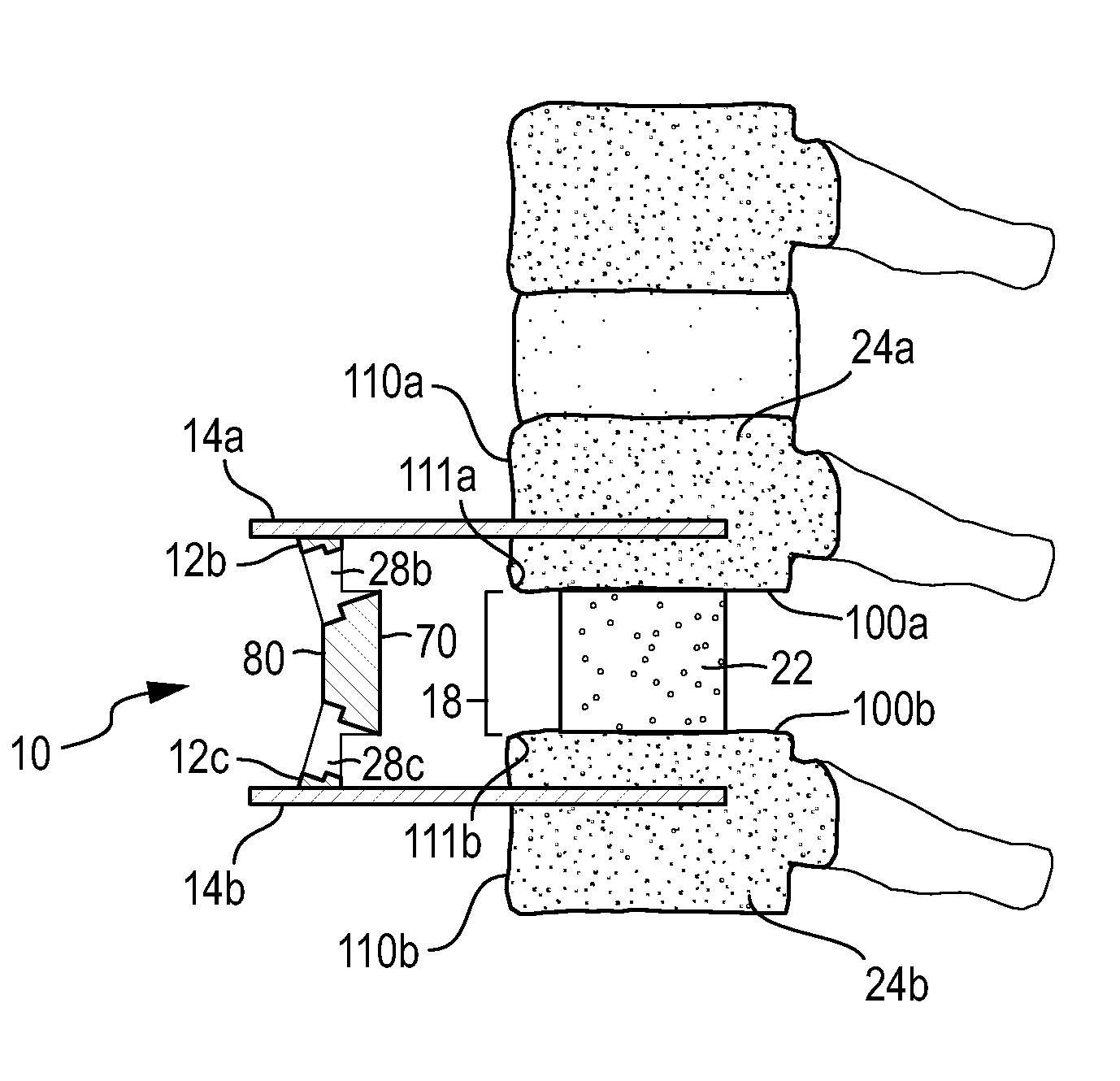
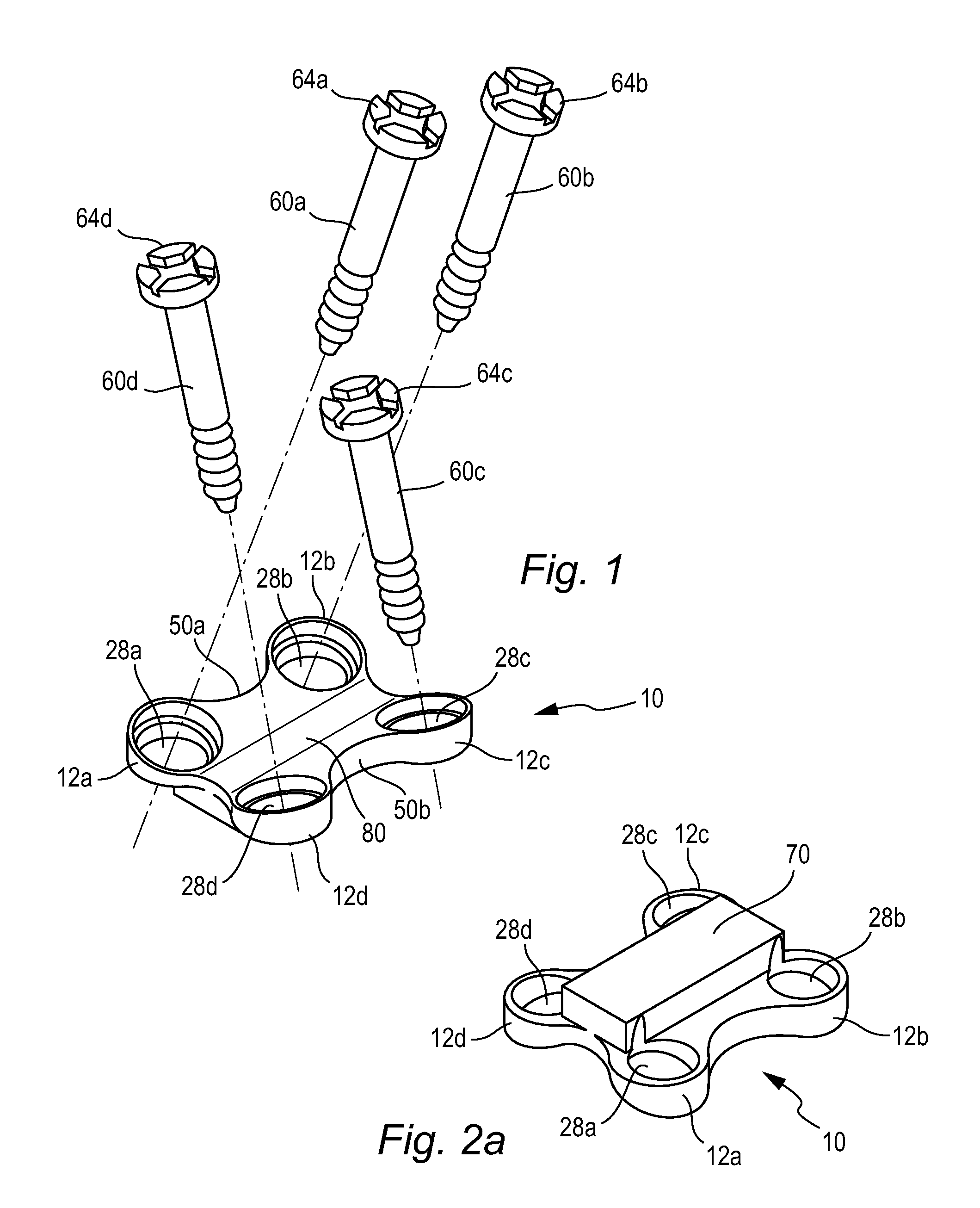
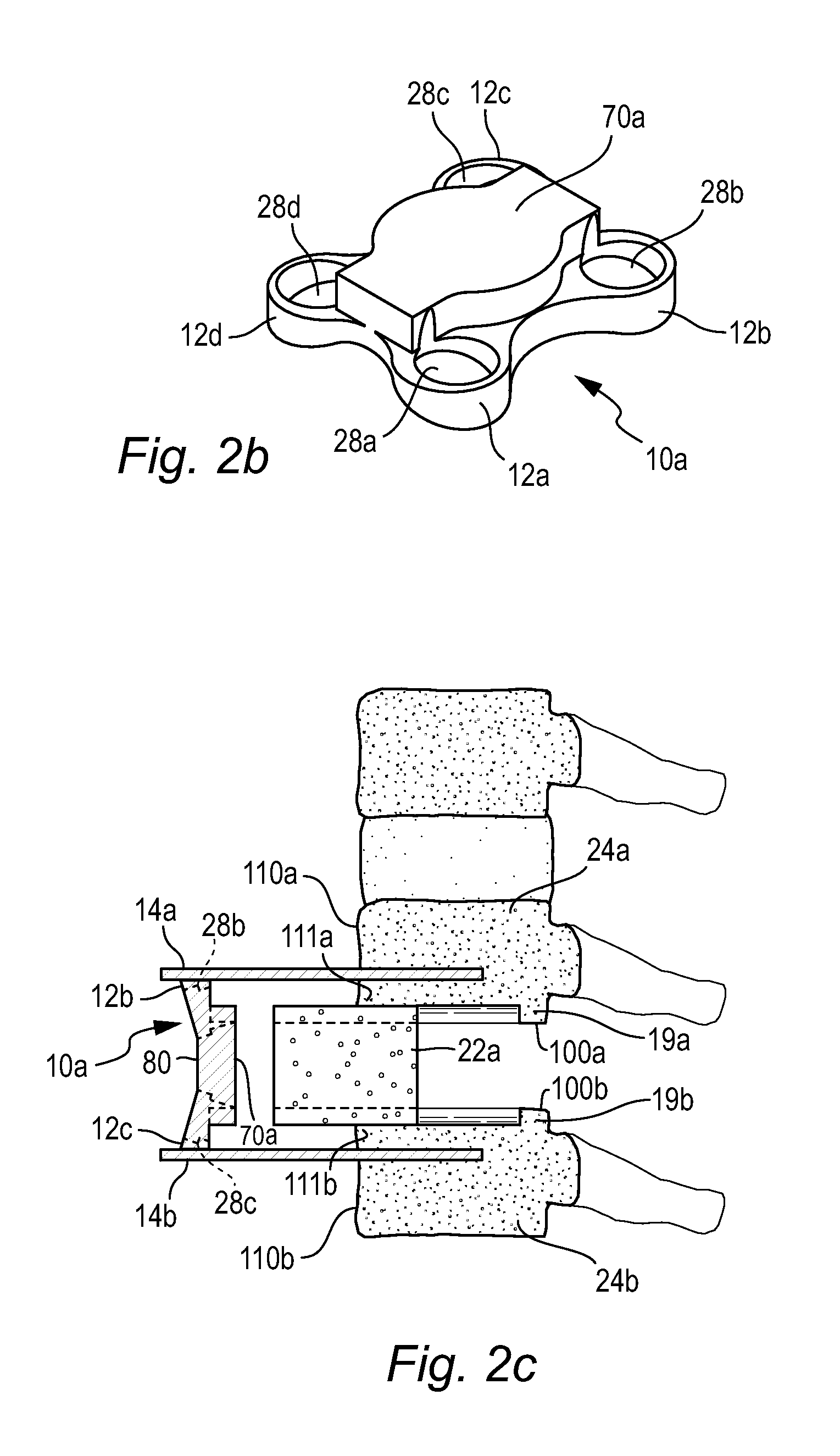
[0030]FIGS. 1, 2a, and 3 show an unhinged vertebral plate assembly 10, FIG. 2a shows an alternative unhinged vertebral plate 10a having an alternative posterior face 70a, FIG. 2c shows an alternative vertebral plate 10a and alternative graft 22a being implanted, FIG. 2d shows anterior view of an alternate graft 22a implanted into an intervertebral space, FIGS. 4-6 show a vertebral plate assembly 10 being implanted, FIGS. 8-9 shown a hinged vertebral plate assembly 10b, and FIGS. 10-11 shown an implanted hinged plate assembly 10g. Methods provided herein for installing the non-hinged vertebral plate assemblies 10 and 10a c...


PUM


Abstract

Low-profile anterior vertebral plate assemblies and methods of use are disclosed herein. The plate assemblies herein are useful for coupling adjacent vertebral bodies together. Preferred vertebral plates assemblies herein are low-profile, meaning that the assemblies herein are positioned partially within and partially outside of the intervertebral space. Additional teachings are directed to hinged low-profile anterior vertebral plate assemblies that allow slight flexion towards the vertebral bodies in a sufficient amount to prevent kyphosis, and encourage a desired amount of lordosis.

Description

FIELD OF THE INVENTION[0001]The embodiments herein relate to low-profile anterior vertebral plates and methods of use in spinal fixation procedures. More particularly, the teaching herein relate to improving current methods and systems directed to fusing one or more adjacent vertebrae.BACKGROUND[0002]The spine consists of a series of bone structures termed “vertebrae.” Between each vertebra is a flexible, connective tissue termed an “intervertebral disc” which secures one vertebrae to another and functions as a shock absorber. Spinal fixation is a surgical technique in which one or more vertebrae are joined by an implant (e.g., a plate or rods.) to prevent relative movement of the spine, with the goal of live bone eventually fusing the adjacent vertebrae together.[0003]Patients requiring spinal fusion typically suffer from either neurological deficits or severe pain which has not responded to conservative treatment. Typical conditions that are treated by spinal fusion procedure non-...

Claims


Application Information

Patent Timeline
Patent Type & Authority Applications(United States)
IPC IPC(8): A61B17/88A61B17/70
CPCA61B17/7059A61F2310/00161A61F2/44A61F2/4455A61F2002/30471A61F2002/30576A61F2002/30578A61F2002/30785A61F2002/30787A61F2002/30789A61F2002/444A61F2310/00011A61F2310/00017A61F2310/00023A61B17/7077A61B17/70A61B17/8004A61B17/8061
Inventor NEHLS, DANIEL
Owner NEHLS DANIEL
Learn More