Load mitigation device for wind turbine blades

a technology of load mitigation device and wind turbine blade, which is applied in the direction of rotors, passive/reactive control, vessel construction, etc., can solve the problems of serious damage, detriment to the performance and lifetime of the blade,

Inactive Publication Date: 2012-03-15
SIEMENS AG
View PDF3 Cites 7 Cited by
  • Summary
  • Abstract
  • Description
  • Claims
  • Application Information

AI Technical Summary

Problems solved by technology

In this case, the lift generated by the wind turbine blade is highly detrimental to the performance and lifetime of the blade and can cause serious damage.

Method used


Image

  • Load mitigation device for wind turbine blades
  • Load mitigation device for wind turbine blades
  • Load mitigation device for wind turbine blades

Examples


Embodiment Construction

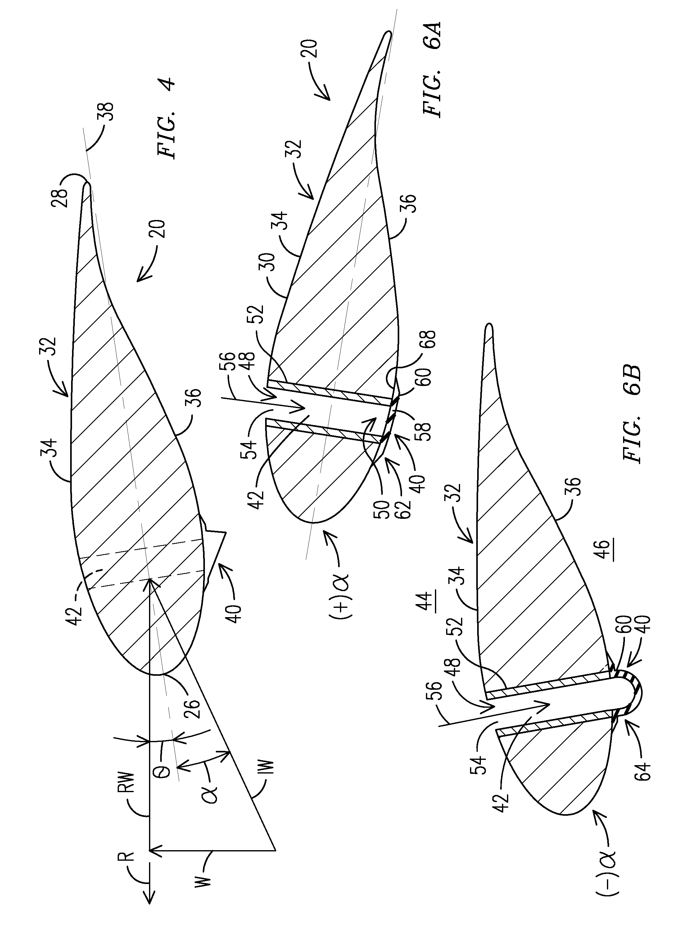
[0016]The present inventors have innovatively developed a load mitigation device for use with wind turbine blades and a wind turbine blade incorporating the device. When activated, the load mitigation device will lower the detrimental forces generated by a wind turbine blade. For example, when the angle of attack of wind impinging upon a wind turbine blade is negative, the pressure difference between opposed surfaces of the wind turbine blade activates a load mitigation device that will change shape to lower the lift generated by the blade while increasing the generated drag. Typically, the loss of lift is significantly larger than the gain in drag. The mitigation in loads on the wind turbine blade can lead to an increased lifetime of the existing blades and of newly manufactured blades.

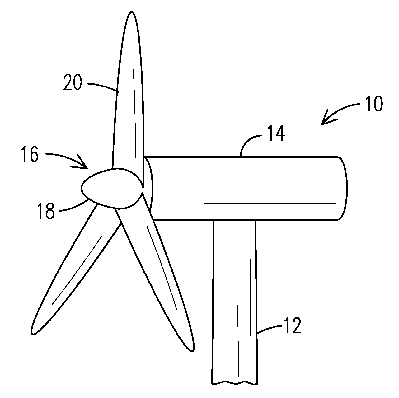
[0017]Now referring to the figures, FIG. 1 illustrates a wind turbine 10 having a tower 12, a nacelle 14 mounted on the tower 12, and a rotor 16 having a hub 18 and a plurality of rotor blades 20 the...


PUM


Abstract

The present invention includes a rotor blade (20) having a blade body (30) with a leading edge (26) and a trailing edge (28) and opposed first and second surfaces (34, 36) extending there between defining an airfoil shape (32) in cross-section. A passageway (42) extends through the blade body (30) between the first and second surfaces (34, 36). A flexible member (60) is sealed over one end (50) of the passageway (42). Advantageously, the flexible member (60) is passively responsive to changes in a differential pressure between the first and second surfaces (34, 36) to move between a deactivated position (62) and an activated position (64) where the flexible member (60) extends away from the airfoil shape (32) to function as a load mitigation device (40) for the wind turbine rotor blade (20).

Description

FIELD OF THE INVENTION[0001]The present invention relates to wind turbines, and more particularly to a load mitigation device for use in wind turbines.BACKGROUND OF THE INVENTION[0002]Typically, wind turbines include a rotor having a plurality of rotor blades mounted thereon; a drive train and a generator housed in a nacelle; and a tower. The nacelle and the rotor are typically mounted on top of the tower. The blades each include an upwind side and a downwind side. In optimal operation, a pocket of low-pressure air forms on the downwind side of the blade. The low-pressure air pocket pulls the blade toward it, causing the rotor to turn. This is referred to as “lift.” The force of the lift is actually much stronger than the wind's force frictional force opposing motion, which is called “drag.” Lift will always be at a right angle to the wind while drag will follow in the direction of the wind. The combination of lift and drag causes the rotor to spin the blades of the rotor. Both lift...

Claims


Application Information

Patent Timeline
Patent Type & Authority Applications(United States)
IPC IPC(8): F03D7/00
CPCF03D1/0641F03D1/0683F03D7/0252F03D7/0256F05B2240/311Y02E10/723F05B2250/60F05B2270/1095F05B2270/402Y02E10/721F05B2250/02Y02E10/72F03D1/0675
Inventor OBRECHT, JOHN M.STANDISH, KEVIN J.MEDINA, PAUL F.
Owner SIEMENS AG
Why Eureka
Try Eureka