
Object classification

a technology of object classification and object, applied in the field of object classification, can solve the problems of difficult task that requires a skilled operator and sufficient clear conditions, large amount of uncertainty as to the target under observation, and the rise of detection and classification problems

Inactive Publication Date: 2012-03-08
BAE SYSTEMS PLC
View PDF4 Cites 7 Cited by
  • Summary
  • Abstract
  • Description
  • Claims
  • Application Information

AI Technical Summary

Benefits of technology

The present invention provides a method for processing an observation of an object to be classified using a particle filter. This method involves using a plurality of models, each containing a set of particles, to weight the particles based on an observation parameter. The particles are weighted based on the sensed value of the observation parameter and the models are adjusted accordingly. The method may also involve iteratively changing the measurement variable and performing further observations of the object to provide new sensed values for the observation parameter. The classification potential level is determined based on the weightings of the particles and the certainty or uncertainty with which the object can be classified as one of the models. The invention also provides a computer program and apparatus for performing the method.

Problems solved by technology

The problems of detection and classification arise in many fields.
A detection problem is, for example, one of detecting a target object in a certain environment.
A classification problem is, for example, one of determining to which class or group of objects the detected target object belongs.
This is a difficult task that requires a skilled operator and sufficiently clear conditions.
However, there is a large amount of uncertainty as to the target under observation.
Mine detection and classification is currently inefficient, and tends not to be feasible in any but the most benign environments, using a single measurement or observation of a particular facet of a target.
Other mine-classifiers based on analytical models, or state-transition matrices often fail because targets are typically not well represented by simple analytical, or piecewise stationary models.

Method used


Image

  • Object classification
  • Object classification
  • Object classification

Examples


Embodiment Construction

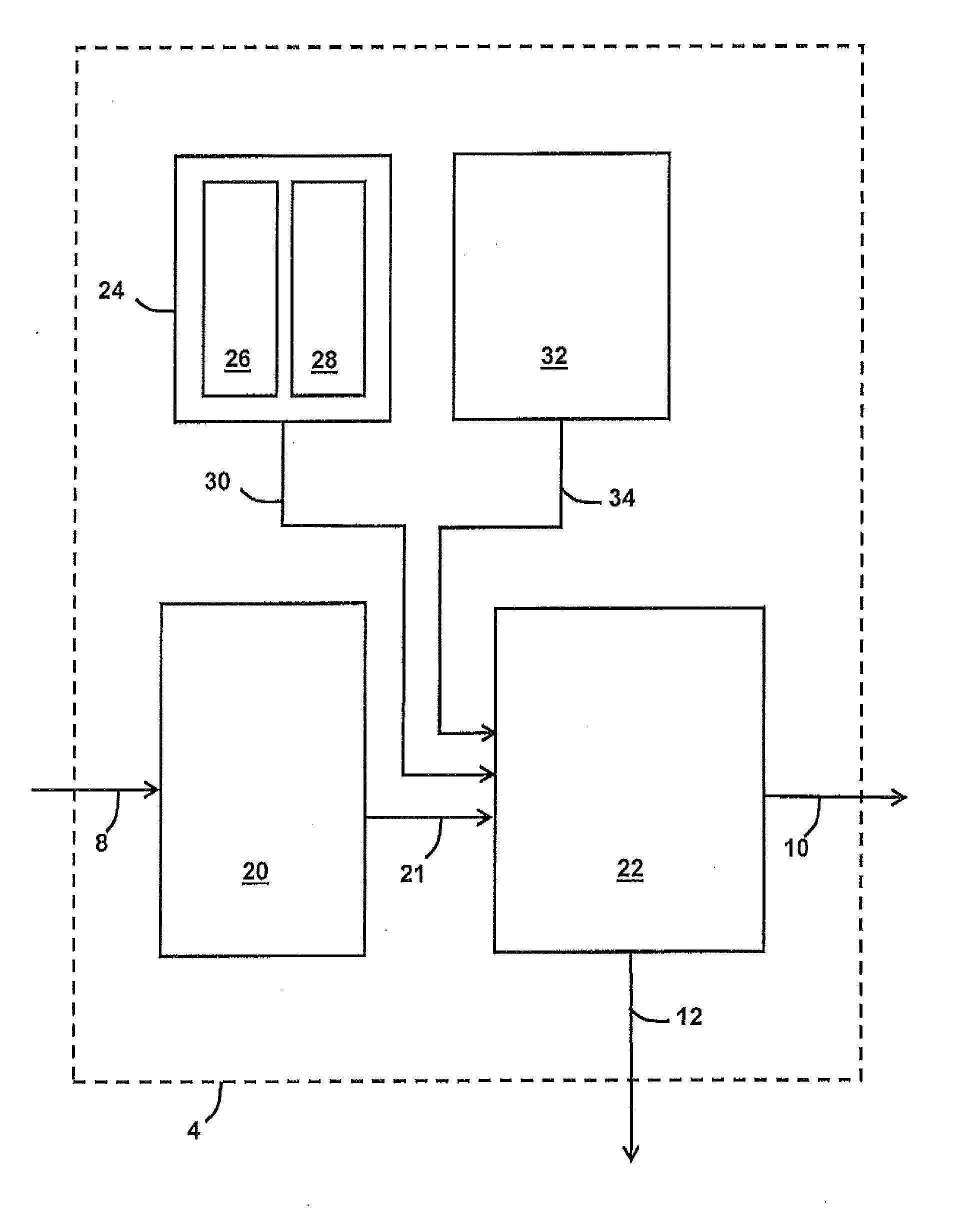
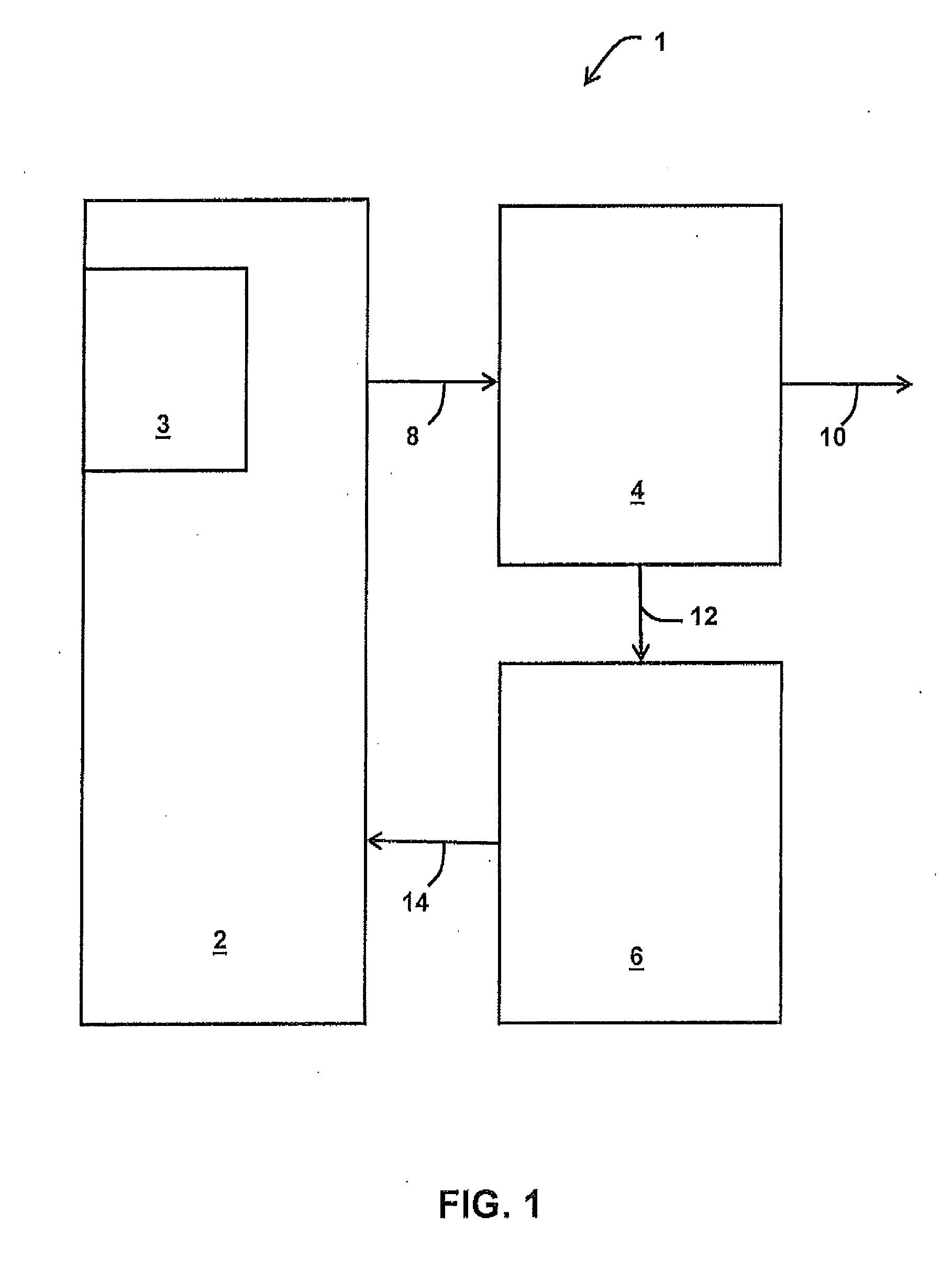
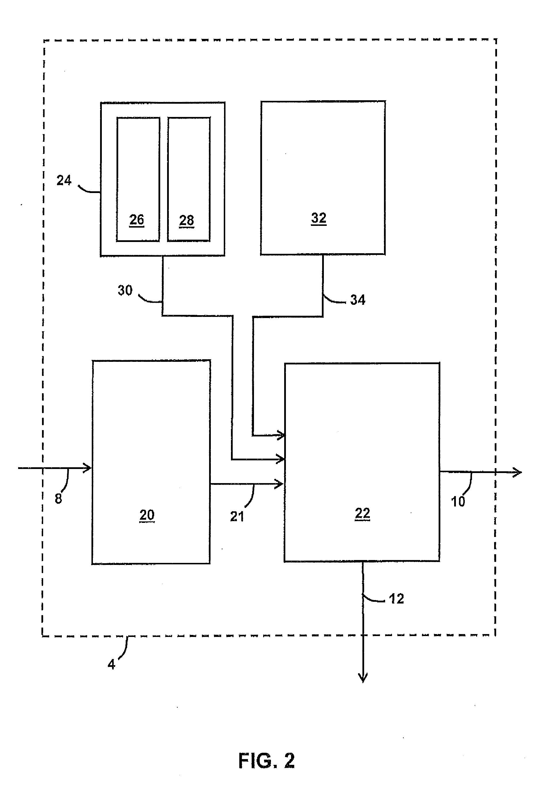
[0046]FIG. 1 is a schematic illustration of a mine detection and classification system 1. The mine detection and classification system 1 comprises a mine-hunting vessel 2, a mine-classifier 4, and a vessel position processor 6.

[0047]The mine-hunting vessel 2 is an Autonomous Underwater Vehicle (AUV). The mine-hunting vessel 2 comprises a sensor 3. The sensor 3 is forward-looking sonar. The sensor 3 makes observations of a target (not shown), for example the sensor 3 measures a physical quantity of the target, and converts the observations into a signal, hereinafter referred to as “input data 8”, in a conventional way. In this embodiment, the target for the mine-hunting vessel 2 is identified by a target identifying vessel (not shown). In this example, the input data 8 comprises data representative of the observation of the target and data representative of the angle of the target relative to the mine-hunting vessel 2, i.e. the three dimensional bearing of the target from the mine-hu...


PUM


Abstract

A method and apparatus for processing an observation of an object to be classified, the method comprising using a particle filter in which an observation of an object to be classified is used to weight particles on a plurality of models for the object. The method may further comprise performing at least one further iteration of using the particle filter to weight the particles on the plurality of models for the object using a further observation of the object to be classified. The method may further comprise providing respective classification probabilities that each respective model corresponds to the object based on the weightings of the particles of the respective model. Each of the respective particles may be divided into a respective plurality of sub-particles.

Description

FIELD OF THE INVENTION[0001]The present invention relates to processing observations of an object to be classified, and determining classification probabilities for classifying objects according to sensed observation measurements, and classifying objects.BACKGROUND[0002]The problems of detection and classification arise in many fields. A detection problem is, for example, one of detecting a target object in a certain environment. A classification problem is, for example, one of determining to which class or group of objects the detected target object belongs. An example field in which detection and classification problems arise is the field of mine counter measures (MCM). In the field of mine counter measures, the classification of a detected object is required to be performed in order to identify the detected object as a mine, and ideally a particular type of mine.[0003]Current mine counter measures rely on an operator interpreting signals, for example from Sonar and / or an electro-...

Claims


Application Information

Patent Timeline
Patent Type & Authority Applications(United States)
IPC IPC(8): G06F17/30
CPCB63G7/00B63G2007/005G06K9/6268G01S15/88G06K9/00496G01S7/539G06F2218/00G06F18/241
Inventor BARR, JORDI MCGREGORLLOYD, CHRISTOPHER MARKNICHOLSON, DAVIDWILLIAMS, MARK LAWRENCE
Owner BAE SYSTEMS PLC
Learn More