
Identifying An End Of An Electrical Cord

Inactive Publication Date: 2012-03-01
IBM CORP
View PDF20 Cites 2 Cited by
  • Summary
  • Abstract
  • Description
  • Claims
  • Application Information

AI Technical Summary

Problems solved by technology

As such, system administrators are subject to accidentally disconnecting the wrong electrical line cord, thereby unnecessarily causing a power failure on a computer in the data center or unintentionally causing some other error.

Method used


Image

  • Identifying An End Of An Electrical Cord
  • Identifying An End Of An Electrical Cord
  • Identifying An End Of An Electrical Cord

Examples


Embodiment Construction

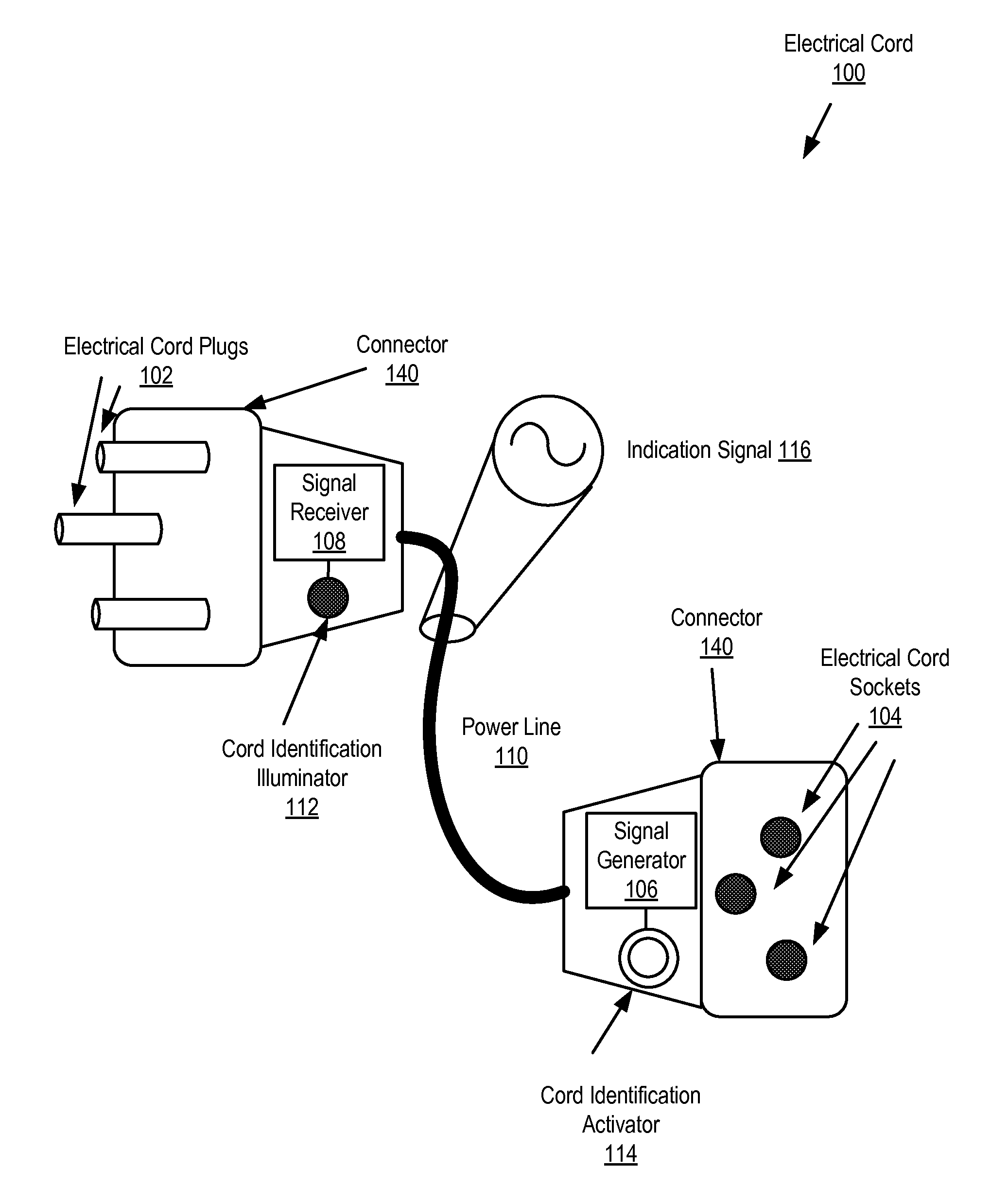
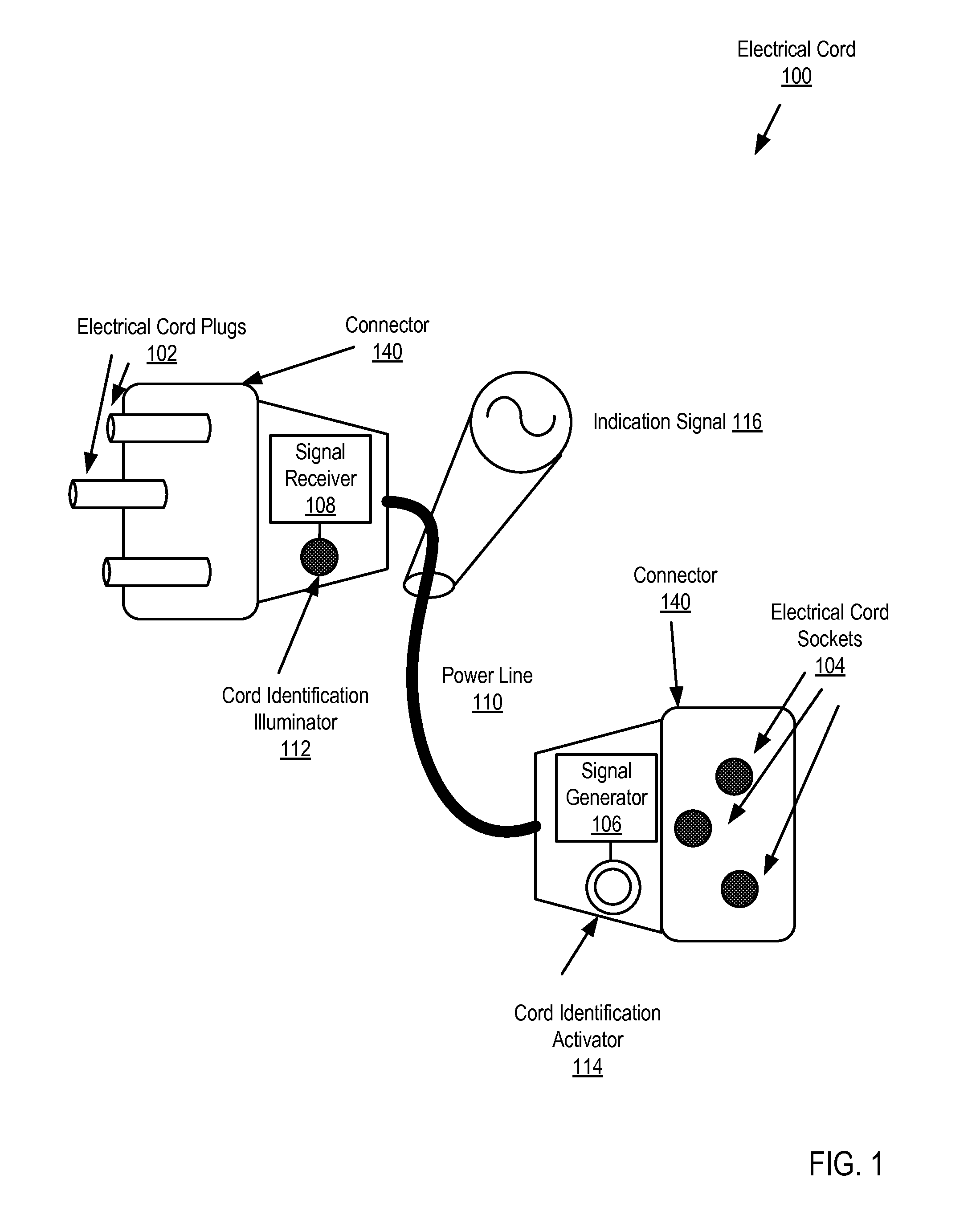
[0013]Exemplary methods and systems for identifying an end of the electrical cord in accordance with the present invention are described with reference to the accompanying drawings, beginning with FIG. 1. FIG. 1 sets forth a line drawing of an electrical cord (100) according to embodiments of the present invention. The electrical cord (100) of FIG. 1 includes a power line (110) for transmission of electrical power from one end of the electrical cord to the other end of the electrical cord. The power line (110) of FIG. 1 is a combination of electrical wires that enables electric current to flow between ends of the power line (110). The power line (110) is used to transmit an electric current to provide power from one end of the electrical cord (100) to the other end of the electrical cord (100).

[0014]At each end of the power line (110) is a connector (140) that is used to connect the electrical cord (100) to another device, cord, or power supply. At one end of the electrical cord (10...


PUM


Abstract

An electrical cord is disclosed that includes a power line for transmitting electric current from one end of the electrical cord to the other end of the electrical cord. The electrical cord also includes a cord identification activator integrated into at least one end of the power line and coupled for data communications through the power line to a cord identification illuminator. The activator includes a signal generator for sending an indication signal to the illuminator through the power line in response to a user's activation of the activator. The illuminator illuminates in response to receiving the indication signal from the signal generator.

Description

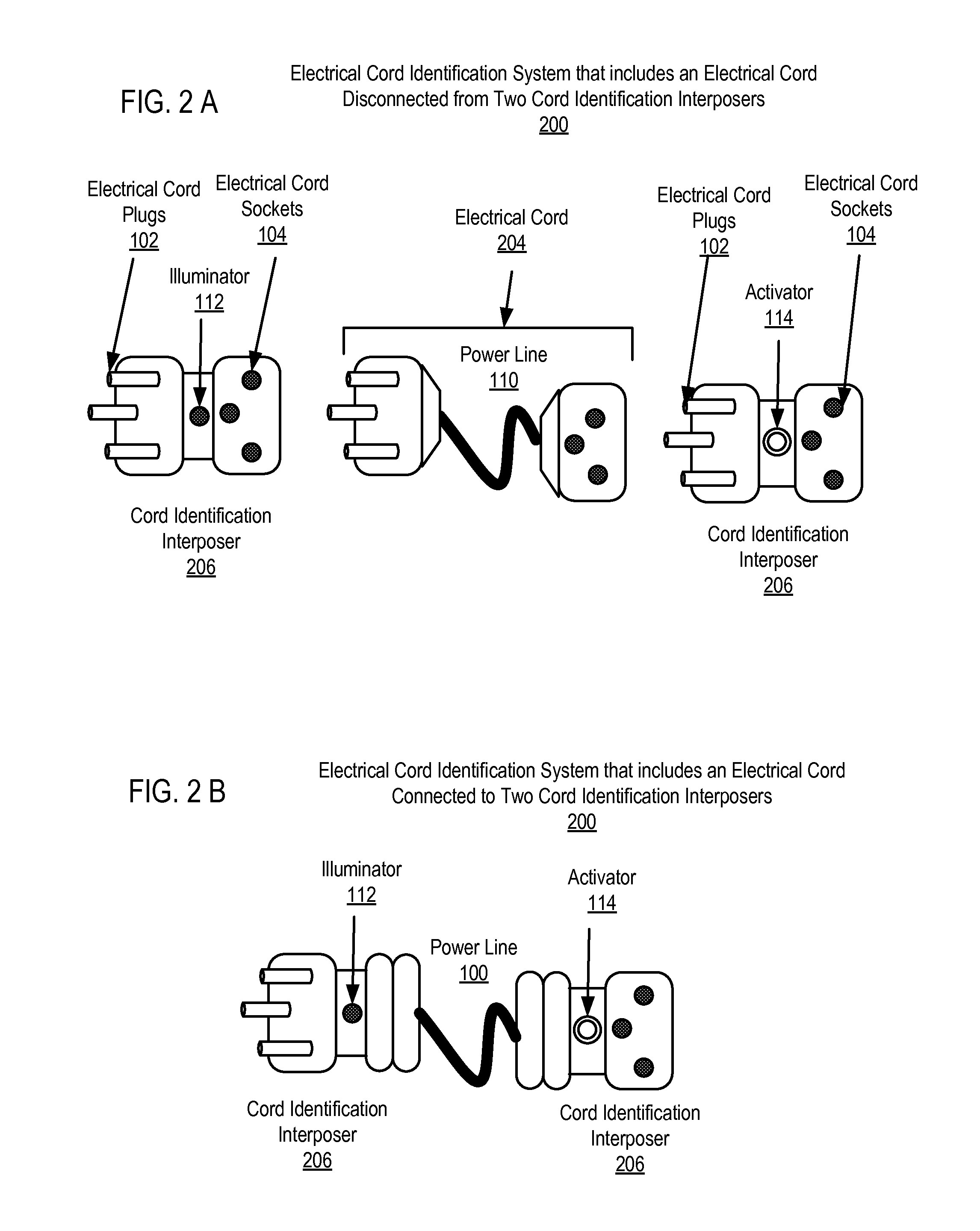
BACKGROUND OF THE INVENTION[0001]1. Field of the Invention[0002]The field of the invention includes methods and systems for identifying an end of an electrical cord.[0003]2. Description of Related Art[0004]A typical data center may utilize a large number of electrical line cords to connect devices to other electrical cords or to other devices. These cords often become tangled with one another and therefore the ability of a system administrator to identify the proper end of a particular electrical cord to either connect or disconnect may be reduced. As such, system administrators are subject to accidentally disconnecting the wrong electrical line cord, thereby unnecessarily causing a power failure on a computer in the data center or unintentionally causing some other error.SUMMARY OF THE INVENTION[0005]An electrical cord is disclosed that includes a power line for transmitting electric current from one end of the electrical cord to the other end of the electrical cord. The electrical...

Claims


Application Information

Patent Timeline
Patent Type & Authority Applications(United States)
IPC IPC(8): G09F9/33G08B5/00
CPCH02G2200/20H02G1/00H01R31/065
Inventor ARCHIBALD, MATTHEW R.BUTERBAUGH, JERROD K.
Owner IBM CORP
Learn More