Support frame for radiation shield garment & methods of use thereof

Inactive Publication Date: 2012-03-01
GOLD DEBORAH L +2
View PDF5 Cites 1 Cited by
  • Summary
  • Abstract
  • Description
  • Claims
  • Application Information

AI Technical Summary

Benefits of technology

[0005]Each shoulder member may comprise: (i) base; and (ii) a shoulder bracket projecting upwardly in a curved manner from the base for extending over shoulders of a wearer. The base may include one or more slots providing angular adjustment of the pair of shoulder members and wherein one or more fasteners extend through the one or more slots slideably attaching the each shoulder member to the upper top end of the elongated upper vertical back member. The support frame may further comprise one or more inwardly facing upper padded members coupled to the base of the each of the pair of shoulder members and positioned to rest upon a shoulder area of the wearer.
[0006]The upper bottom end of the elongated upper vertical back member may include one or more longitudinal slots; and wherein one or more fastening means extend through the elongated slots providing vertical height adjustment of the elongated upper vertical back member. The lower back support

Problems solved by technology

Generally, such radiation shield garments are extremely heavy because they include one or more layers of lead sheet material to provide the desired protection.
Extended use of such garments may become burdensome and tiring to the wearer with extended use.
This is particularly true when the weight of the garment is borne primarily and / or unremittingly by the wearer's shoulders and neck.
Since users (or wearers), such as x-ray technicians, radiologists, etc. frequently have to wear them for extended periods of time, they often become tiring and even painful, particularly when the sole or primary support is substantially or constantly one portion of the wearer's body.
The shoulders, because of their physiological structure and their relatively high position on the body as a whole, are particularly susceptible to these effects.

Method used


Image

  • Support frame for radiation shield garment & methods of use thereof
  • Support frame for radiation shield garment & methods of use thereof
  • Support frame for radiation shield garment & methods of use thereof

Examples


Embodiment Construction

[0016]The following detailed description is of the best currently contemplated modes of carrying out the invention. The description is not to be taken in a limiting sense, but is made merely for the purpose of illustrating the general principles of the invention.

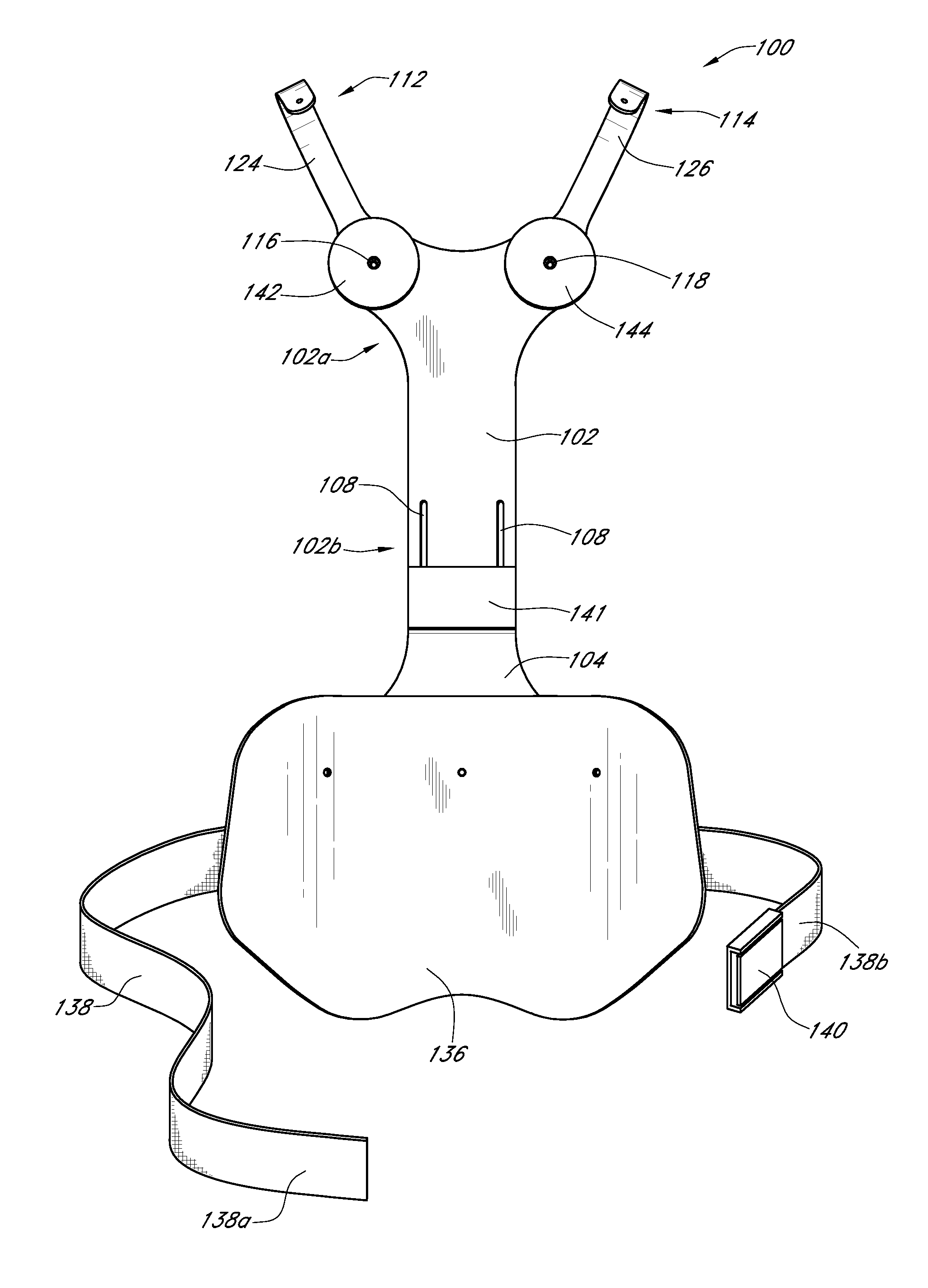
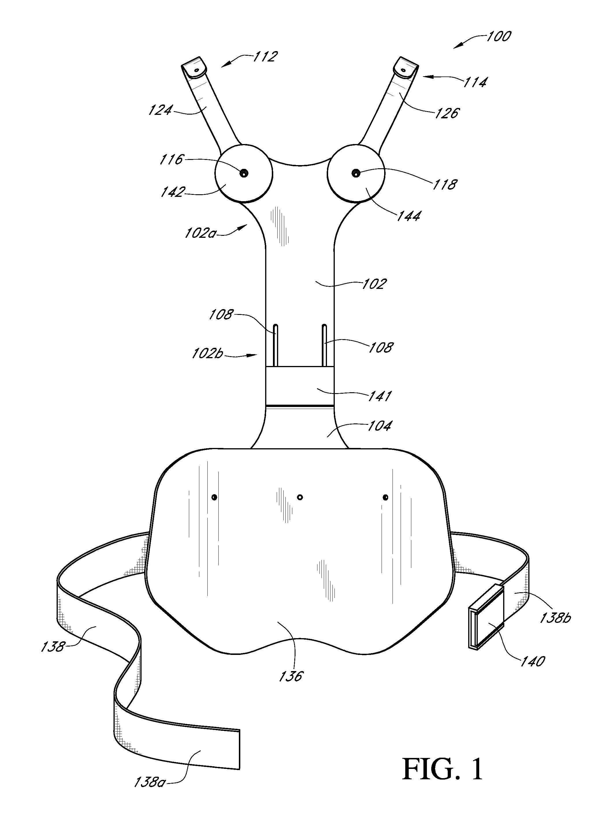
[0017]Embodiments of the invention are directed to a support frame for alleviating the weight and stress inflicted upon the shoulders and neck of individual caused by wearing a radiation shield garment and methods of use thereof. In one embodiment, the support frame comprises an elongated upper vertical back members slidably coupled to a lower vertical back member to provide vertical height adjustment; a lower back support panel coupled to the lower vertical back member to provide lower back support to the wearer; and a pair of shoulder members attached to the upper top end of the elongated vertical back member to support shoulder regions of the radiation shield garment.

[0018]FIG. 1 illustrates a front view of a support fram...


PUM


Abstract

Embodiments of the invention are directed to a support frame for alleviating the weight and stress inflicted upon the shoulders and neck of individual caused by wearing a radiation shield garment and methods of use thereof. In one embodiment, the support frame comprises an elongated upper vertical back members slidably coupled to a lower vertical back member to provide vertical height adjustment; a lower back support panel coupled to the lower vertical back member to provide lower back support to the wearer; and a pair of shoulder members attached to the upper top end of the elongated vertical back member to support shoulder regions of the radiation shield garment.

Description

FIELD OF INVENTION[0001]At least one feature pertains to a support frame for a radiation shield garment and methods of use thereof.BACKGROUND OF INVENTION[0002]It is well-known to provide protective garments to personnel working in or near a radioactive environment, to health care workers operating x-ray equipment or working in radiology laboratories. Generally, such radiation shield garments are extremely heavy because they include one or more layers of lead sheet material to provide the desired protection. Extended use of such garments may become burdensome and tiring to the wearer with extended use. This is particularly true when the weight of the garment is borne primarily and / or unremittingly by the wearer's shoulders and neck. For example, persons exposed to x-rays typically wear aprons and / or other apparel made from material having a large lead and / or other heavy metal content, designed to absorb harmful radiation to which the user might otherwise be exposed. Such aprons may ...

Claims


Application Information

Patent Timeline
IPC IPC(8): A41D13/00
CPCA61B6/107
Inventor GOLD, DEBORAH L.FORMAN, STEVEGENNAWEY, DANNY
Owner GOLD DEBORAH L
Why Eureka
Try Eureka