
Blood pressure measuring apparatus

a technology of measuring apparatus and blood pressure, which is applied in the field of blood pressure measuring apparatus, can solve the problems of difficult to measure the correct blood pressure from the oscillation signal, and the period of oscillation

Active Publication Date: 2012-02-23
NIHON KOHDEN CORP
View PDF4 Cites 16 Cited by
  • Summary
  • Abstract
  • Description
  • Claims
  • Application Information

AI Technical Summary

Benefits of technology

[0005]It is therefore an object of the invention to provide a blood pressure measuring apparatus which can solve the problem that oscillation due to driving of the air pump is superimposed as noise on an oscillation signal and an accurate blood pressure cannot be obtained.

Problems solved by technology

In the process of inflating the cuff pressure, however, air is ejected from an air pump to a cuff, and hence periodic oscillation due to driving of the air pump is superimposed as noise on pressure oscillation in the cuff caused by pulsation.
In the case where the cycle of the oscillation due to driving of the air pump is similar to that of the pulsation component which is a principal component of a pulse wave, therefore, it is difficult to measure a correct blood pressure from the oscillation signal.

Method used


Image

  • Blood pressure measuring apparatus
  • Blood pressure measuring apparatus
  • Blood pressure measuring apparatus

Examples


Embodiment Construction

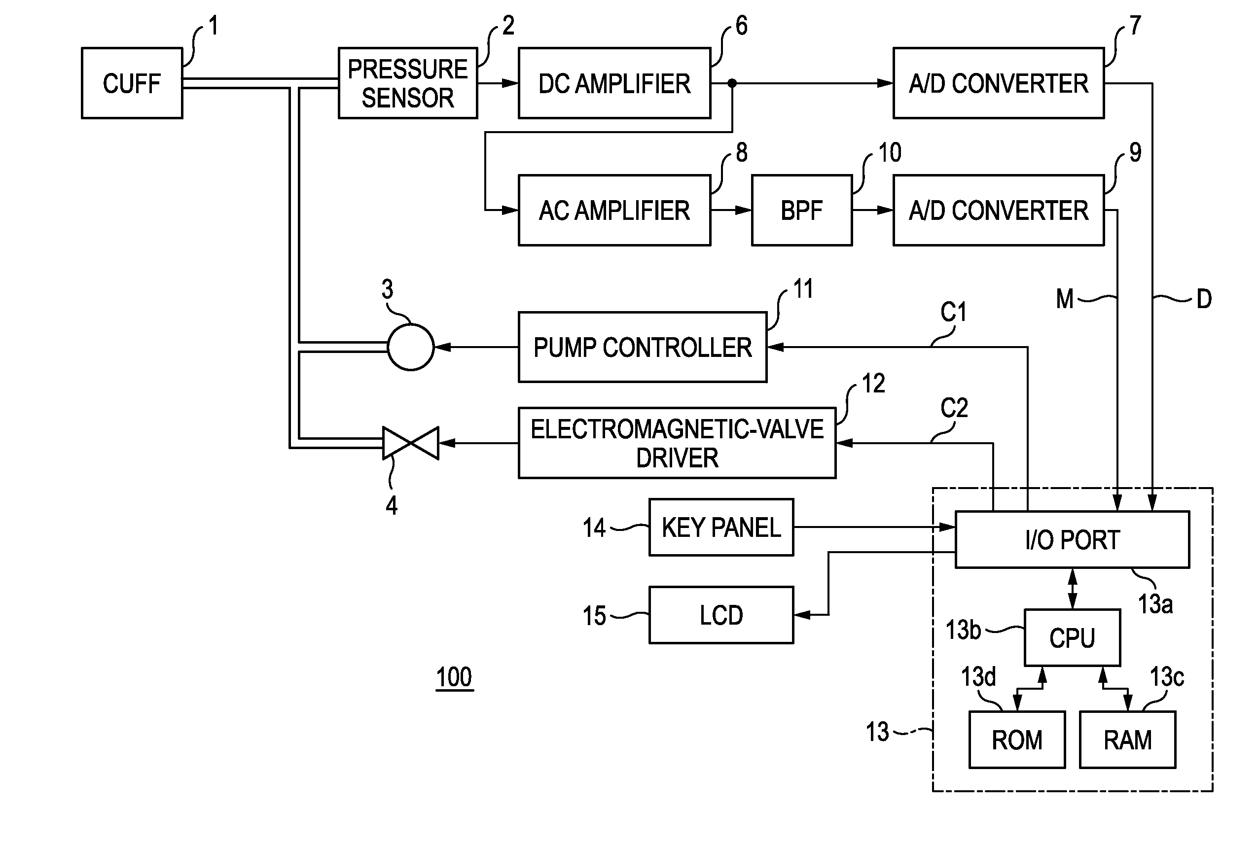
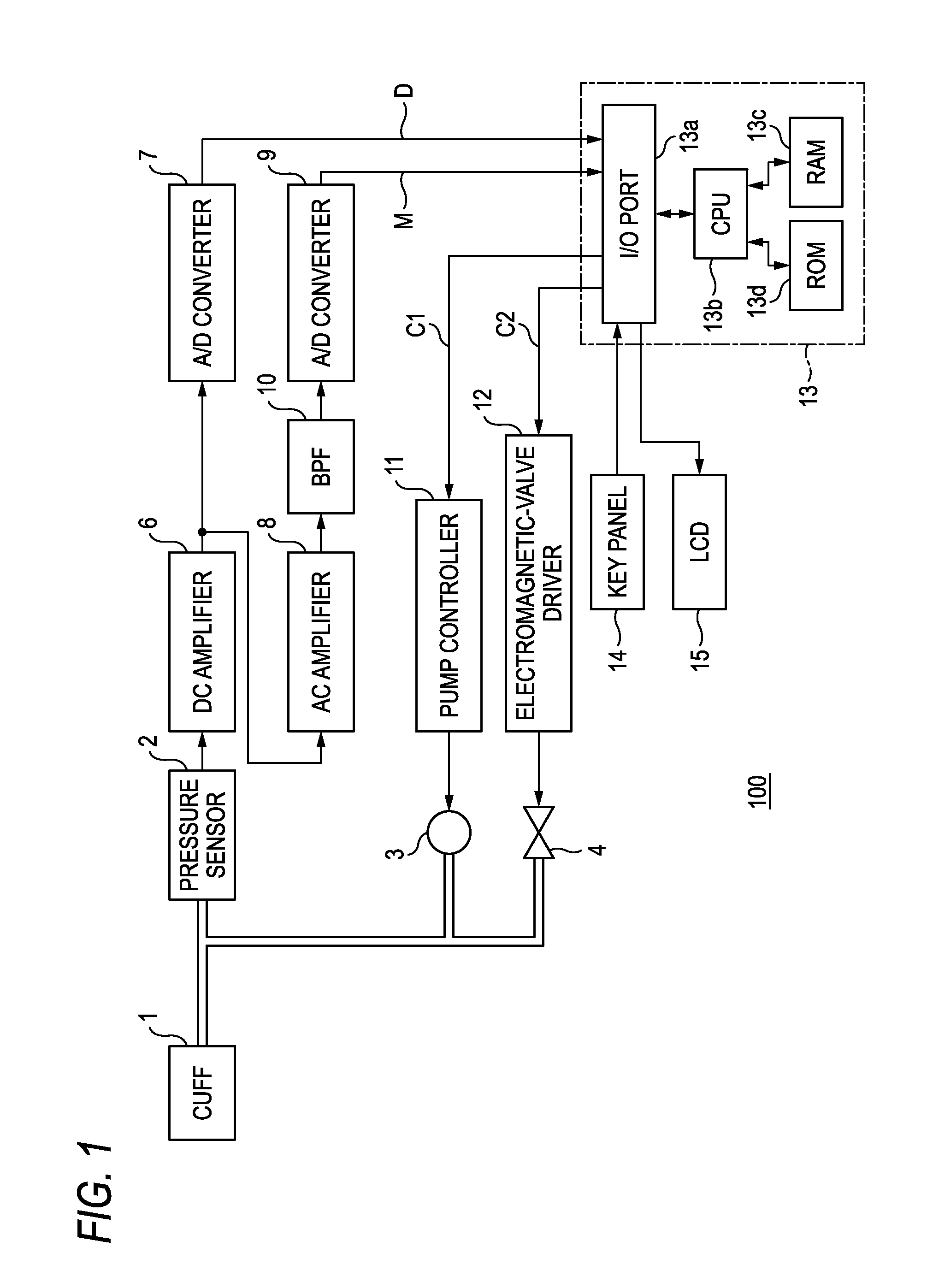
[0022]Hereinafter, a blood pressure measuring apparatus 100 of an embodiment of the invention will be described in detail with reference of the drawings. FIG. 1 is a functional block diagram schematically showing the blood pressure measuring apparatus 100. As shown in FIG. 1, the blood pressure measuring apparatus 100 includes a cuff 1, a pressure sensor 2, an air pump 3, an electromagnetic valve 4, a DC amplifier 6, A / D converters 7, 9, an AC amplifier 8, a BPF (Band Pass Filter) 10, a pump controller 11, an electromagnetic-valve driver 12, a controller 13, a key panel 14, and a liquid crystal display (LCD) 15.

[0023]In the blood pressure measuring apparatus 100, the pump controller 11, the air pump 3, the electromagnetic-valve driver 12, the electromagnetic valve 4, and the controller 13 function as the cuff-pressure control unit in the invention to control a cuff pressure of a cuff that presses a part of a living body.

[0024]The pressure sensor 2, the DC amplifier 6, the A / D conver...


PUM


Abstract

A blood pressure measuring apparatus, which measures a blood pressure of a living body, includes: a cuff-pressure control unit which controls a cuff pressure of a cuff that presses a part of the living body; an oscillation signal detection unit which detects an oscillation signal from the cuff pressure; a blood pressure specification unit which specifies systolic and diastolic blood pressures as the blood pressure of the living body from the oscillation signal; and a blood pressure determination unit which determines whether systolic and diastolic blood pressures are appropriate or not. The cuff-pressure control unit controls the cuff pressure to be inflated to a first set value, the blood pressure specification unit specifies the systolic and diastolic blood pressures based on a change of an oscillation signal that is detected by the oscillation signal detection unit when the cuff pressure is inflated to the first set value, and when the blood pressure determination unit determines that both the systolic and diastolic blood pressures are appropriate, the cuff-pressure control unit ends the inflating of the cuff pressure to release the cuff pressure.

Description

BACKGROUND OF THE INVENTION[0001]The present invention relates to a blood pressure measuring apparatus which non-invasively measures the blood pressure.[0002]As a blood pressure measuring apparatus which non-invasively measures the blood pressure, a blood pressure measuring apparatus is usually employed in which the blood pressure is measured by first inflating the cuff pressure to a pressure that is sufficiently higher than the systolic blood pressure (for example, a cuff pressure that is higher than the systolic blood pressure by 40 mmHg), and, while then deflating the cuff pressure, detecting pressure oscillation that is produced in the cuff pressure by pulsation, as an oscillation signal. There is a blood pressure measuring apparatus in which the blood pressure is measured while inflating the cuff pressure, in order to shorten the time required for measurement as compared with the blood pressure measurement that measures the blood pressure while deflating the cuff pressure (for ...

Claims


Application Information

Patent Timeline
Patent Type & Authority Applications(United States)
IPC IPC(8): A61B5/0225
CPCA61B5/02116A61B5/0225A61B5/02225A61B5/02141
Inventor USUDA, TAKASHIKIKUCHI, YOSHIHARUHIRAHARA, HIDEAKIKOBAYASHI, NAOKISUZUKI, KATSUYOSHI
Owner NIHON KOHDEN CORP
Learn More