Position measuring apparatus, position measuring method, image processing apparatus and image processing method

Active Publication Date: 2012-02-23
PANASONIC CORP
View PDF0 Cites 18 Cited by
  • Summary
  • Abstract
  • Description
  • Claims
  • Application Information

AI Technical Summary

Benefits of technology

[0011]The present invention has been conceived to solve the aforementioned conventional problem with an aim to provide a position measuring apparatus and a position measuring method for measuring a position of a position measurement target with ease and a high precision without using any parameters stored inside a camera when measuring the position of the position measurement target, based on a plurality of images captured from mutually different viewpoints.
[0013]With this structure, it is possible to measure the three-dimensional position of the position measurement target, using ray information which associates each of ray vectors indicating the forward direction of light incident onto the optical system for each of input images with a corresponding one of the pixels in the input image. Accordingly, it is possible to measure the position of the position measurement target with ease and a high precision without using the parameters stored inside the camera.
[0015]With this structure, it is possible to correct distortion in the input images, using ray information in which each of the ray vectors indicating the forward direction of light incident onto the optical system for each of input images with is associated with the corresponding one of the pixels in the input image. Accordingly, it is possible to correct the distortion in the input images with ease and a high precision without using the parameters stored inside the camera.
[0017]According to the present invention, it is possible to measure the position of a position measurement target with ease and a high precision without using any parameters inside a camera when measuring the position of the position measurement target, based on a plurality of images captured from mutually different viewpoints.FURTHER INFORMATION ABOUT TECHNICAL BACKGROUND TO THIS APPLICATION

Problems solved by technology

For this reason, in the case where an acrylic hemispherical dome for dust and water prevention is attached to a small omnidirectional camera, it is impossible to exactly calculate the refractive index in each of points in the dome, and thus to obtain accurate corresponding points by performing optical calculations.
This produces a problem that large errors are included in the position measurement results.

Method used


Image

  • Position measuring apparatus, position measuring method, image processing apparatus and image processing method
  • Position measuring apparatus, position measuring method, image processing apparatus and image processing method
  • Position measuring apparatus, position measuring method, image processing apparatus and image processing method

Examples


embodiment 1

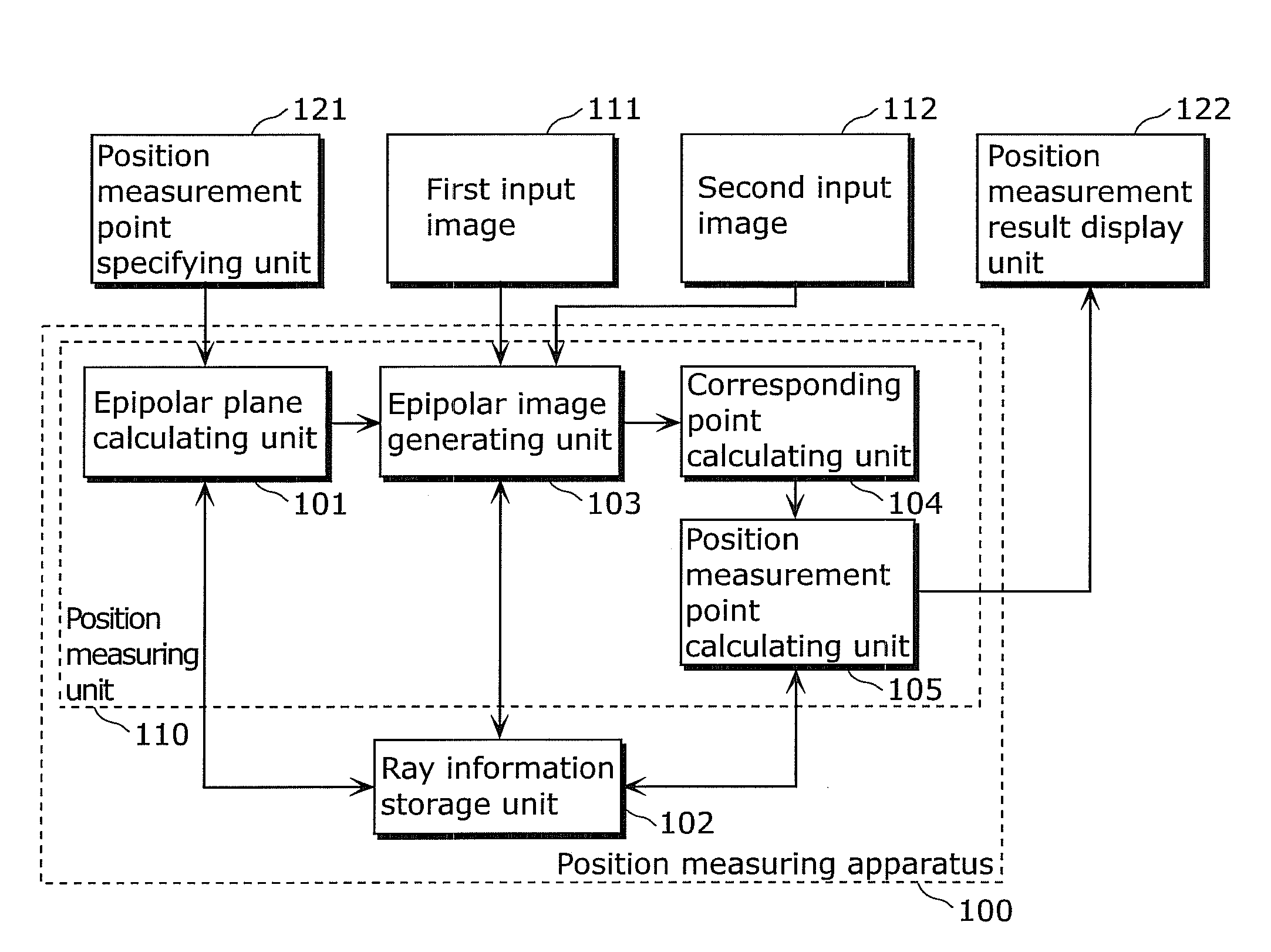
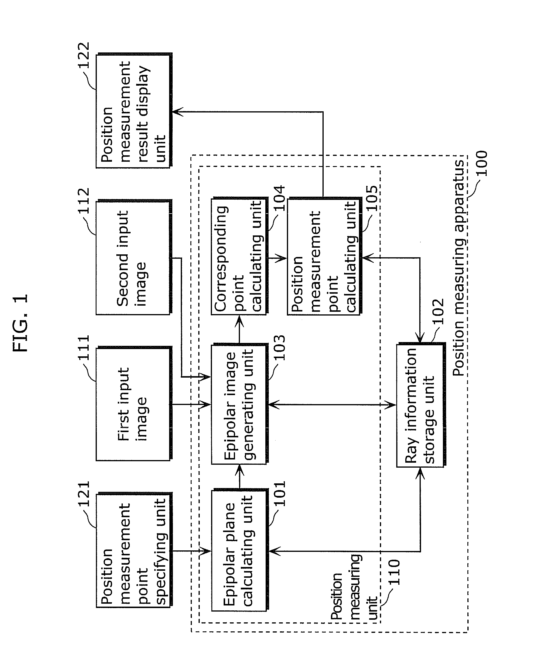
[0037]FIG. 1 is a block diagram showing a structure of a position measuring system according to Embodiment 1 of the present invention.

[0038]In FIG. 1, the position measuring system includes a position measuring apparatus 100, a position measurement point specifying unit 121, and a position measurement result display unit 122.

[0039]The position measurement point specifying unit 121 specifies image coordinates of a point (position measurement point) at which a position measurement target is positioned. The point is in one of images among a first input image 111 and a second input image 112 captured from mutually different viewpoints such that the position measurement target is included in the images. Next, the position measurement point specifying unit 121 transmits the image coordinates of the position measurement point to an epipolar plane calculating unit 101 included in the position measuring apparatus 100.

[0040]The position measurement result display unit 122 displays, on the ima...

embodiment 2

[0140]Next, Embodiment 2 of the present invention is described.

[0141]FIG. 11 is a block diagram showing a structure of a position measuring apparatus 1100 according to Embodiment 2 of the present invention. In FIG. 11, the same structural elements as in FIG. 1 are assigned with the same numerical references, and the same descriptions thereof are not repeated here. The position measuring apparatus 1100 includes a position measurement frame detecting unit 1101, and a position measurement point synthesizing unit 1102.

[0142]When a first input image 111 (or a second input image 112) is input, the position measurement frame detecting unit 1101 corrects distortion of an omnidirectional image by panoramic extension or the like. Subsequently, with reference to a learning database, the position measurement frame detecting unit 1101 detects, using an image recognition technique, an image area including at least one of a person, a face, or a particular object in the first input image 111, and a...

embodiment 3

[0153]Unlike Embodiments 1 and 2 each showing an example of position measurement, Embodiment 3 shows an example of an image processing apparatus which generates an image (that is, a distortion-corrected image) of the orthogonal coordinate system which is closer to an image that is actually viewed by human beings, by utilizing ray information of an image of the polar coordinate system captured using an omnidirectional camera or the like. Such a distortion-corrected image is mainly used by a monitoring camera or the like, and is conventionally generated using parameters stored inside a camera. However, in this embodiment, such a distortion-corrected image is generated by utilizing the ray information as in Embodiments 1 and 2. In this way, even when an acrylic hemispherical dome for dust and water prevention is attached to a small omnidirectional camera, it is possible to perform highly accurate distortion correction without using such parameters stored inside a camera nor performing ...


PUM


Abstract

A position measuring apparatus which measures a position of a position measurement target easily and accurately without using any parameter inside a camera in the measurement, based on images captured from mutually different viewpoints. The position measuring apparatus which measures the three-dimensional position of the position measurement target, based on the input images captured from the mutually different viewpoints, and the position measuring apparatus includes: a ray information storage unit configured to store ray information in which each of ray vectors is associated with a corresponding one of pixels in one of the input images, each of the ray vectors indicating a forward direction of a light incident onto an optical system for a corresponding one of the input images; and a position measuring unit configured to measure the three-dimensional position of the position measurement target, using the ray information stored in the ray information storage unit.

Description

BACKGROUND OF THE INVENTION[0001](1) Field of the Invention[0002]The present invention relates to a position measuring apparatus and a position measuring method for measuring a position of a position measurement target, based on a plurality of images captured from mutually different viewpoints.[0003](2) Description of the Related Art[0004]A monitoring camera which captures images of a suspicious person, package, vehicle, or the like, and / or a navigation system of a moving or mobile robot require(s) detailed three-dimensional position information of objects present in a range of 360 degrees.[0005]As a typical means for obtaining three-dimensional coordinates, stereoscopic viewing is known which involves detecting corresponding points between images captured by cameras arranged at mutually different viewpoints such that ranges for capturing images are overlapped with each other, and calculating three-dimensional distances between the cameras and the objects based on the amounts of dis...

Claims


Application Information

Patent Timeline
IPC IPC(8): G06K9/00
CPCG06T7/0065G06T7/0042G06T2200/21G06T2207/30201G06T2207/10152G06T2207/20021G06T2207/30196G06T2207/10012G06T7/73G06T7/55
Inventor ISHIGAMI, TOMOHIDENISHIMURA, AKIOOKUYAMA, TETSURO
Owner PANASONIC CORP
Why Eureka
Try Eureka