
Focusing Mechanisms for Compressive Imaging Device

a compression imaging and focusing mechanism technology, applied in the field of compression sensing, can solve the problems of large number of samples generated, affecting image reconstruction quality, and overwhelming data volum

Inactive Publication Date: 2012-02-16
INVIEW TECH CORP
View PDF23 Cites 69 Cited by
  • Summary
  • Abstract
  • Description
  • Claims
  • Application Information

AI Technical Summary

Benefits of technology

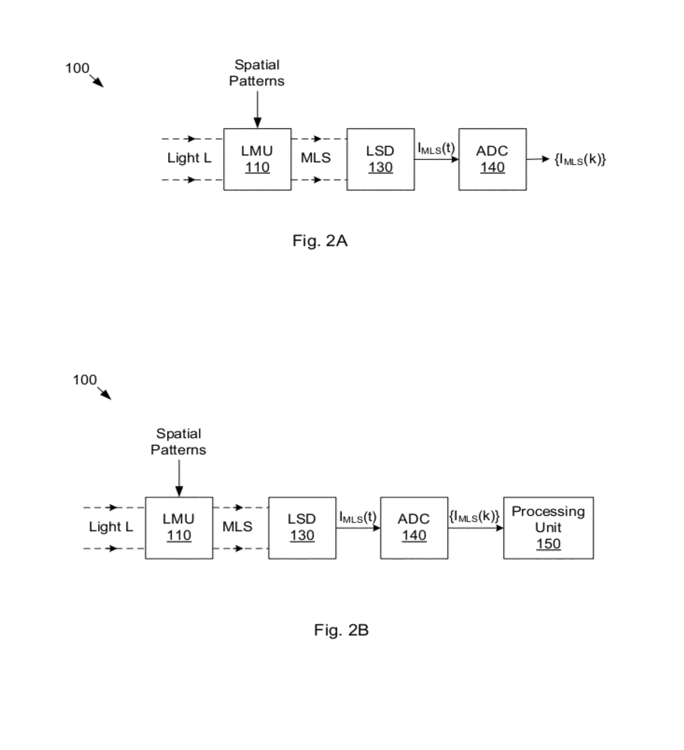
[0021]In one method, the sequence of spatial patterns is configured to effect the movement of a region along a 1D path on the field of the light modulator. Thus, the corresponding samples from the light sensing device represent a one-dimensional image. The 1D image may be analyzed using any of a variety of techniques to derive a value indicating the extent to which the incident light is in focus at the modulator. The focus setting of the input optical subsystem and / or position of the light modulator may be translated until the focus indicator is optimized. (This method may be practiced even when the light sensing device includes an array of light sensing elements, by summing the samples from the elements to obtain one sum value per spatial pattern. The 1D image is then based on the sequence of sum values.) Alternatively, the 1D image may be displayed, allowing a user to control adjustments to focus based on perceived quality of the 1D image.
[0022]In another method, the sequence of spatial patterns may be configured to support the reconstruction of images. Groups of the samples are used to reconstruct corresponding images. The images may be analyzed to determine a focus indicator value for each image (or for selected ones of the images). Again, the focus-determining parameters of the CI device may be adjusted until the 2D focus metric is optimized. Alternatively, the reconstructed image may be displayed, allowing the user to control adjustments to focus based on perceived quality of the 1D image.

Problems solved by technology

A fundamental problem with any attempt to capture a signal x(t) according to Nyquist theory is the large number of samples that are generated, especially when B (or B-A) is large.
The same problem of overwhelming data volume is experienced when attempting to capture an image according to Nyquist theory.
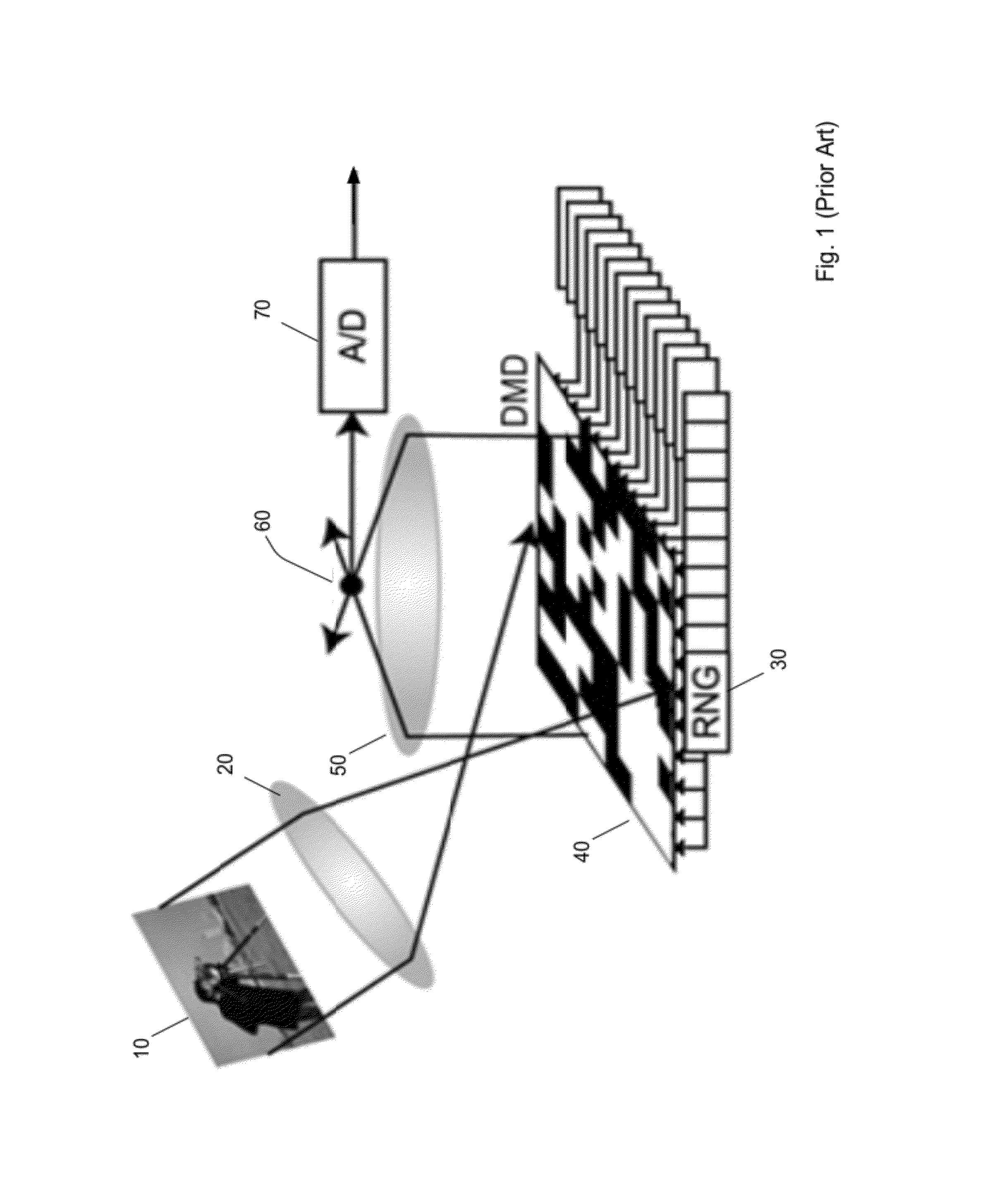
In a compressive imaging (CI) device such as described above, the incident light field needs to be properly focused on the DMD or the quality of image reconstruction will suffer.
However, when the light sensing array is not properly positioned or oriented with respect to the modulated light stream and / or the post-modulation optics, light from the arbitrary region will spill over (cross over) to light sensing elements other than the respective lights sensing element.
The spill over is large when the light sensing array is far from its optimal position or orientation.
Thus, portions of modulated light that spilled over from the other regions to the particular light sensing device have no way of being algorithmically mapped to their correct spatial locations.

Method used


Image

  • Focusing Mechanisms for Compressive Imaging Device
  • Focusing Mechanisms for Compressive Imaging Device
  • Focusing Mechanisms for Compressive Imaging Device

Examples


Embodiment Construction

[0079]The following patent applications provide teachings regarding compressive imaging, and each of them is hereby incorporated by reference in its entirety as though fully and completely set forth herein

[0080]U.S. Provisional Application No. 61 / 372,826, filed on Aug. 11, 2010, entitled “Compressive Sensing Systems and Methods”, invented by Richard Baraniuk, Gary Woods, Kevin Kelly, Robert Bridge, Sujoy Chatterjee and Lenore McMackin.

[0081]U.S. Application No. 13 / 193,553, filed on Jul. 28, 2011, entitled “Determining Light Level Variation in Compressive Imaging by Injecting Calibration Patterns into Pattern Sequence”, invented by Richard Baraniuk, Kevin Kelly, Robert Bridge, Sujoy Chatterjee and Lenore McMackin.

[0082]U.S. Application No. 13 / 193,556, filed on Jul. 28, 2011, entitled “Low-Pass Filtering of Compressive Imaging Measurements to Infer Light Level Variation”, invented by Richard Baraniuk, Kevin Kelly, Robert Bridge, Sujoy Chatterjee and Lenore McMackin.

[0083]U.S. Applicat...


PUM


Abstract

A compressive imaging (CI) device including a light modulator and a light sensor (e.g., a single-element sensor or a sensor array). The CI device may support the focusing of light on the light modulator and / or on the light sensor in a number of ways: (1) determining a focus indicator value by analyzing a 1D or 2D image in the incident light field; (2) measuring light spillover between modulator regions and light sensing elements—either at the level of voltage measurements or the level of reconstructed images; (3) measure noise in reconstructed sub-images; (4) measuring an amount high-frequency content in the incident light field; (5) incorporating a range finder to measure distance to the object being imaged; (6) incorporating an image sensor downstream from the modulator; and (7) splitting a portion of the incident light onto an image sensor, prior to the modulator.

Description

RELATED APPLICATION DATA[0001]This application claims the benefit of priority to U.S. Provisional Application No. 61 / 372,826, filed on Aug. 11, 2010, entitled “Compressive Sensing Systems and Methods”, invented by Richard Baraniuk, Gary Woods, Kevin Kelly, Robert Bridge, Sujoy Chatterjee and Lenore McMackin, which is hereby incorporated by reference in its entirety as though fully and completely set forth herein.FIELD OF THE INVENTION[0002]The present invention relates to the field of compressive sensing, and more particularly to systems and methods for focusing a compressive imaging device.DESCRIPTION OF THE RELATED ART[0003]According to Nyquist theory, a signal x(t) whose signal energy is supported on the frequency interval [−B,B] may be reconstructed from samples {x(nT)} of the signal x(t), provided the rate fS=1 / TS at which the samples are captured is sufficiently high, i.e., provided that fs is greater than 2B. Similarly, for a signal whose signal energy is supported on the fre...

Claims


Application Information

Patent Timeline
IPC IPC(8): H04N5/232
CPCG02B26/0833H04N5/335H04N5/238H04N5/2351H04N5/2354H04N25/00H04N23/75H04N23/71H04N23/74
Inventor MCMACKIN, LENOREHEWITT, DONNA E.WESTON, TYLER H.ZOLLARS, BYRON
Owner INVIEW TECH CORP
Learn More