
Metal Tooth For Zipper

a metal tooth and zipper technology, applied in the direction of snap fasteners, slide fasteners, press-button fasteners, etc., can solve the problems of unsmooth closing or opening of metal zippers, and achieve the effect of prolonging the life of metal zippers, avoiding vibration, and enhancing the engagement of zipper tapes

Inactive Publication Date: 2012-02-16
WANG CHING TSUN
View PDF11 Cites 12 Cited by
  • Summary
  • Abstract
  • Description
  • Claims
  • Application Information

AI Technical Summary

Benefits of technology

[0007]The present invention has been accomplished under the circumstances in view. It is the main object of the present invention to provide a metal tooth for metal zipper, which enhances its engagement with the zipper tape, avoiding vibration relative to the zipper tape during operation of the metal zipper and prolonging the lifespan of the metal zipper.
[0008]It is another object of the present invention to provide a metal tooth for metal zipper, which reduces friction when the metal zipper is opened or closed, facilitating smooth operation of the metal zipper.
[0009]To achieve these and other objects of the present invention, a metal tooth for metal zipper has a mounting hole located on one end of the base thereof, two first engagement portions and two second engagement portions formed integral with the base at two opposite sides of the mounting hole for engaging into the top and bottom sides of the inner edge of the respective zipper tape to deform the respective inner edge during installation so that engagement between the zipper tape and the metal tooth is enhanced, avoiding vibration of the metal tooth relative to the zipper tape during operation of the metal zipper and prolonging the lifespan of the metal zipper.
[0010]Further, metal tooth has a concave surface portion formed in the protruding tooth head thereof so that less friction is produced when the metal zipper is closed or opened.

Problems solved by technology

Thus, closing or opening the metal zipper become unsmooth.

Method used


Image

  • Metal Tooth For Zipper
  • Metal Tooth For Zipper
  • Metal Tooth For Zipper

Examples


Embodiment Construction

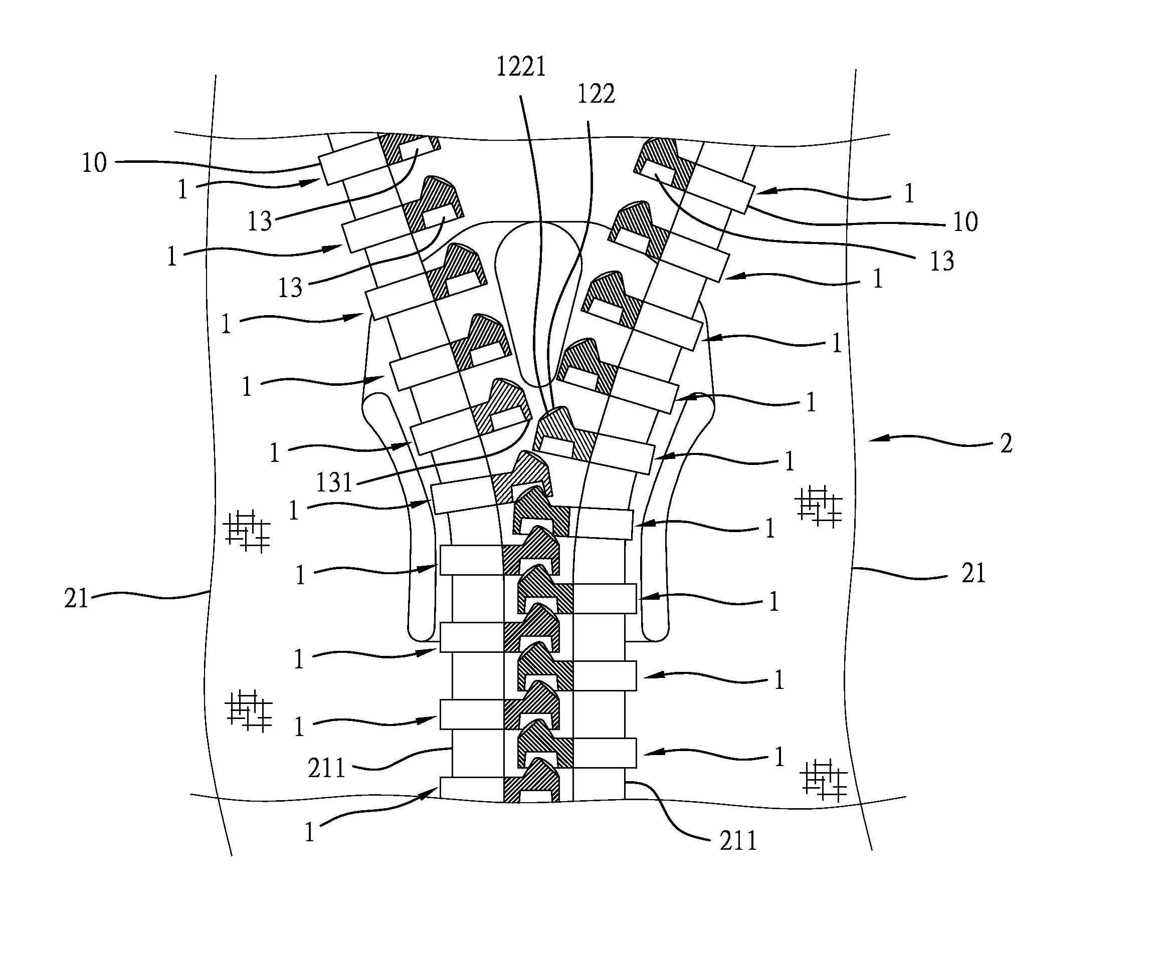
[0018]Referring to FIGS. 4˜7, a metal zipper 2 (see FIG. 7) is shown, comprising two zipper tapes 21 each having a longitudinal inner edge 211, two series of metal teeth 1 respectively and transversely affixed to the zipper tapes 21 and spaced along the respective longitudinal inner edges 211 in a staggered manner. By means of pulling a slide (not shown) in one direction, the two series of metal teeth 1 can be interlocked, forming a chain. Each metal tooth 1 comprises a base 10, a mounting hole 11 transversely cut through one end, namely, the inner end of the base 10 on the middle (see FIG. 6), and a protruding tooth head 12 protruded from one lateral side of an opposite end, namely, the outer end of the base 10. The mounting hole 11 has an outer open end 111, an inner close end 115, a first neck 112 spaced between the outer open end 111 and the inner close end 115, a second neck 114 spaced between the first neck 112 and the inner close end 115, and a flank portion 113 defined betwe...


PUM


Abstract

In a metal zipper, each metal tooth has a mounting hole located on one end of the base thereof, two first engagement portions and two second engagement portions formed integral with the base at two opposite sides of the mounting hole for engaging into the top and bottom sides of the inner edge of the respective zipper tape to deform the respective inner edge during installation so that engagement between the zipper tape and the metal tooth is enhanced, avoiding vibration of the metal tooth relative to the zipper tape during operation of the metal zipper and prolonging the lifespan of the metal zipper. Further, each metal tooth has a concave surface portion formed in the protruding tooth head thereof so that less friction is produced when the metal zipper is closed or opened.

Description

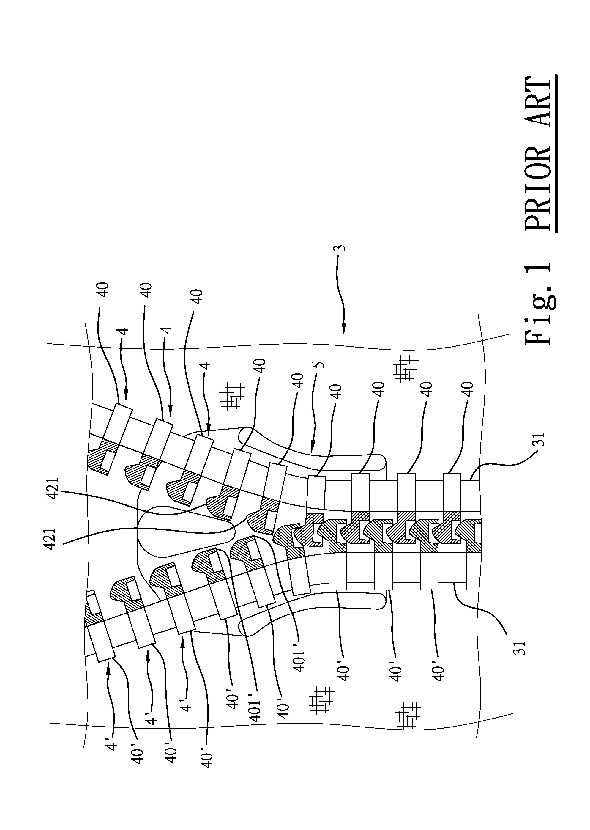
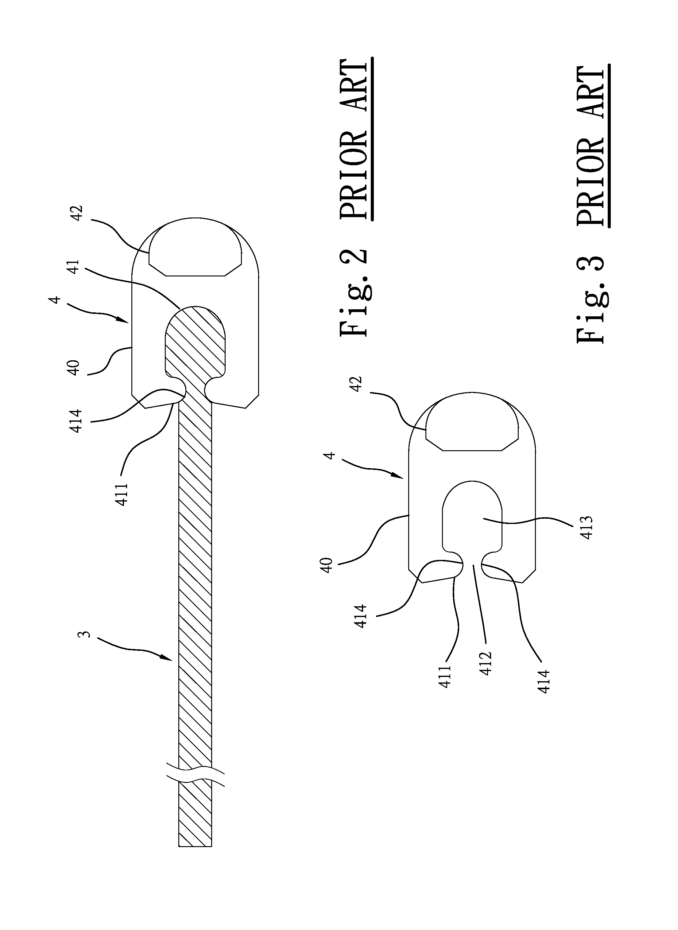
BACKGROUND OF THE INVENTION[0001]1. Field of the Invention[0002]The present invention relates to an improved structure of metal zipper and more particularly, to a metal tooth for zipper, which enhances its engagement with the zipper tape, avoiding vibration relative to the zipper tape during operation of the metal zipper and prolonging the lifespan of the metal zipper. Further, the metal tooth has a concave surface portion formed in the protruding tooth head thereof so that less friction is produced when the metal zipper is closed or opened.[0003]2. Description of the Related Art[0004]In a regular metal zipper, as shown in FIG. 1, metal teeth 4 are respectively fastened to the longitudinal inner edges 31 of the respective zipper tapes 3 by a press or installation tool (not shown). According to this design, each metal tooth 4 comprises a base 40, a mounting hole 41 transversely cut through two opposite lateral sides of the base 40 for mounting. The mounting hole 41 has an outer open ...

Claims


Application Information

Patent Timeline
IPC IPC(8): A44B19/08
CPCA44B19/06Y10T24/2532
Inventor WANG, CHING-TSUN
Owner WANG CHING TSUN
Learn More