
Portable Modular Solar Energy Power Generating System

Inactive Publication Date: 2012-01-12
SORTENTO JERRY MR +1
View PDF4 Cites 7 Cited by
  • Summary
  • Abstract
  • Description
  • Claims
  • Application Information

AI Technical Summary

Problems solved by technology

The available systems are not readily adaptable for temporary remote installations.
Currently available solar energy collecting systems are generally not adapted for easy and quick deployment at remote locations.

Method used


Image

  • Portable Modular Solar Energy Power Generating System
  • Portable Modular Solar Energy Power Generating System
  • Portable Modular Solar Energy Power Generating System

Examples


Embodiment Construction

[0024]The present invention will now be described in terms of the presently preferred embodiment thereof as illustrated in the drawings. This description should not be construed as limiting the scope of the appended claims.

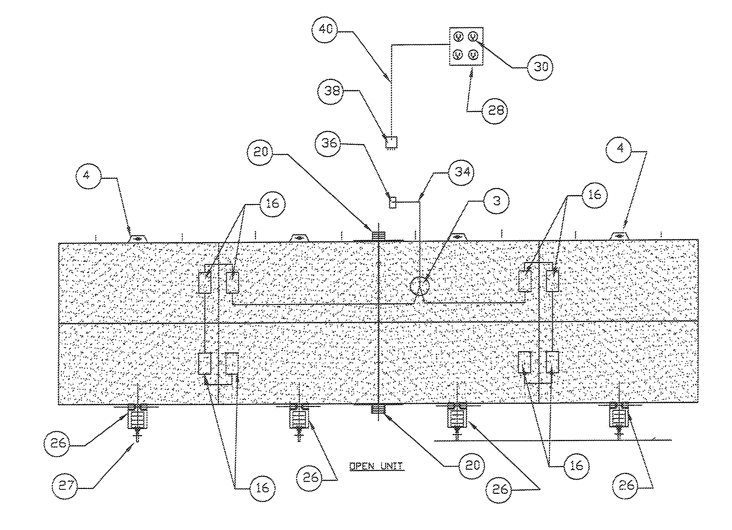
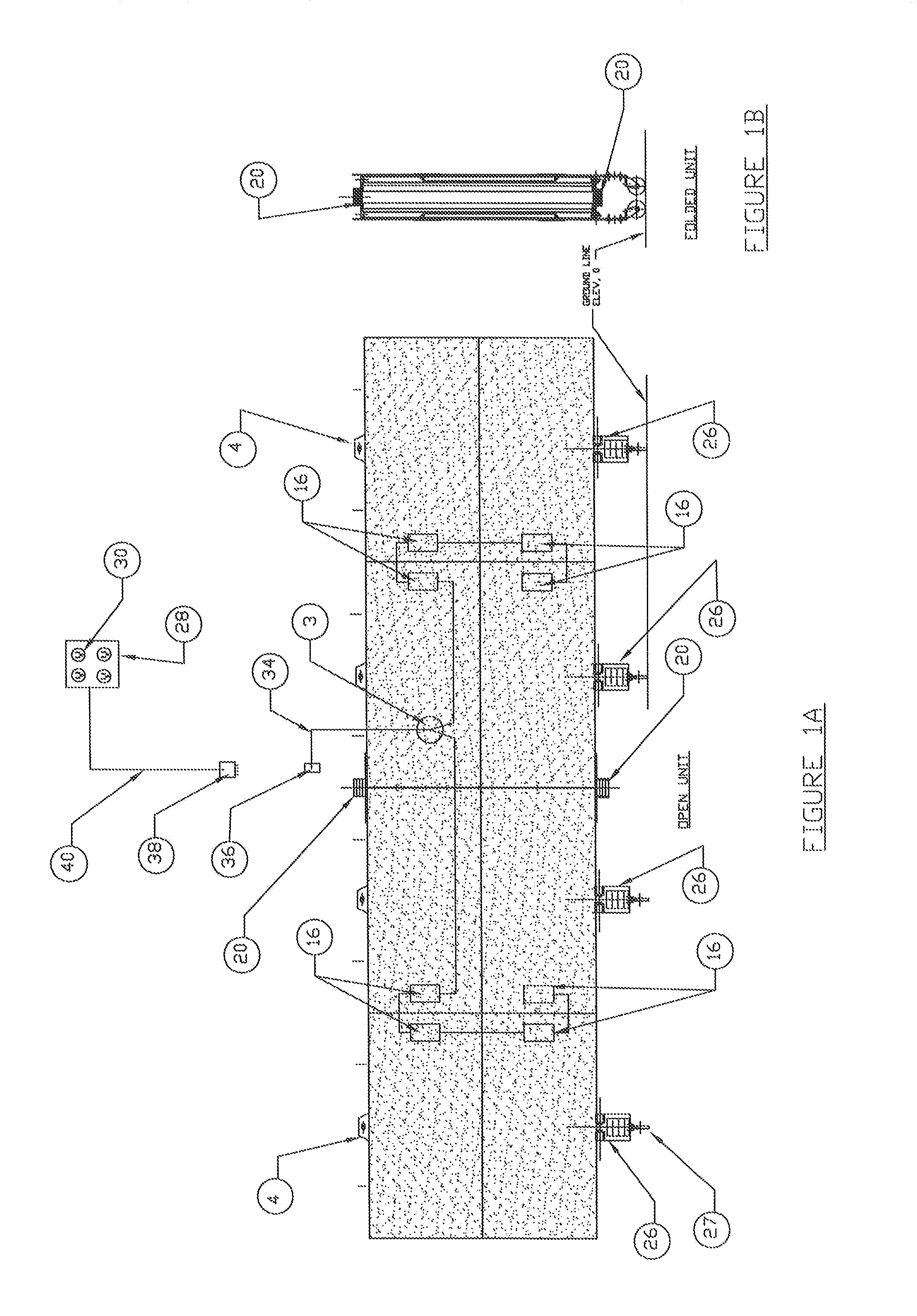
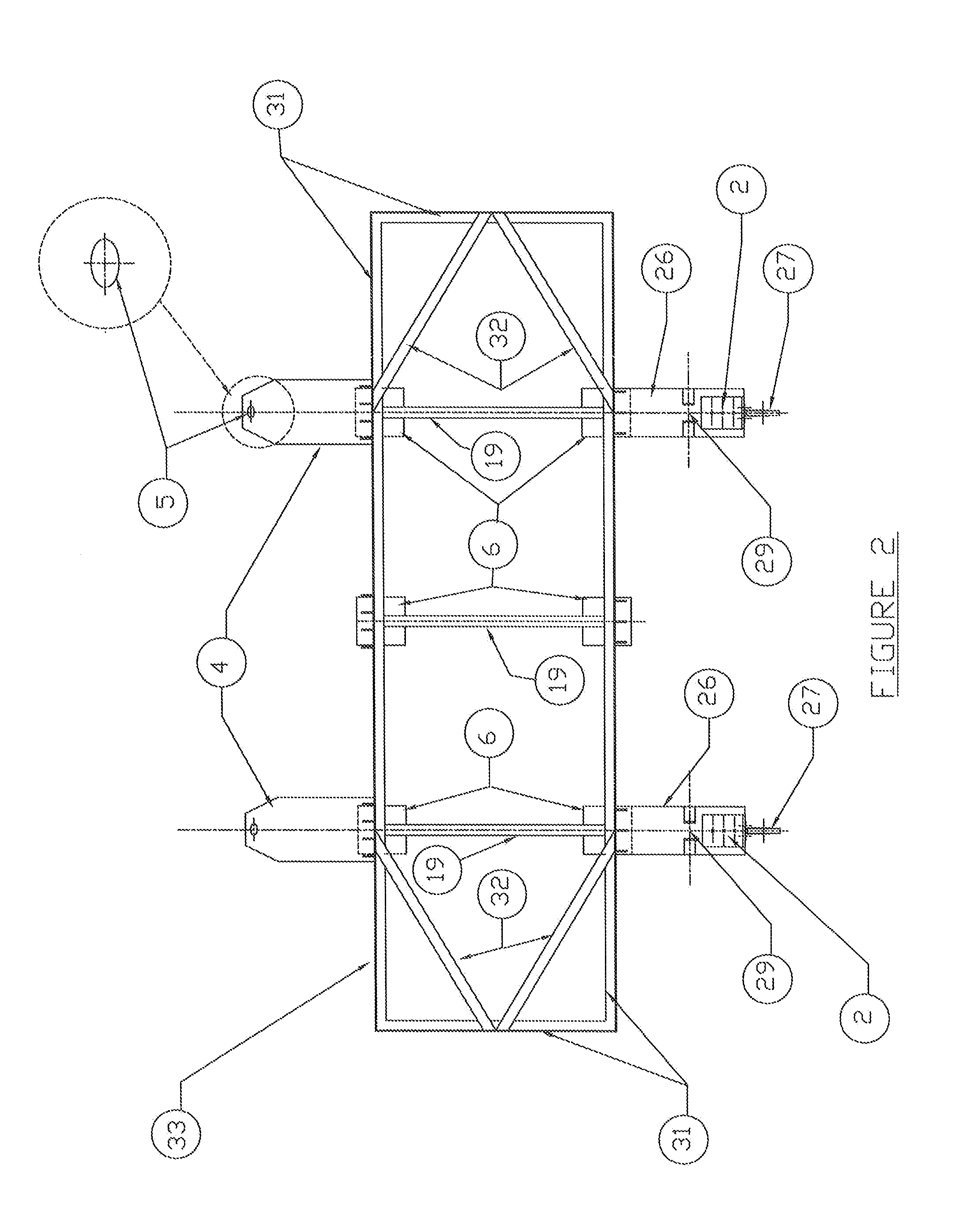
[0025]The Solar Generating System 10 is illustrated in the drawings. As shown therein, the system 10 comprises a plurality of modular units 12 that comprise the Solar Generating System 10. Each of the plurality of modular units 12 comprises a photovoltaic solar panel 14 and a micro-inverter 16. The photovoltaic solar panels 14 are commercially available products that collect and convert solar energy into DC electrical power. The micro-inverter 16 converts the DC power generated by the photovoltaic solar panels 14 to AC current which can be used to power conventional electrically powered devices.

[0026]FIG. 3 illustrates a system whereby the number of modular units 12 is 4 although a greater or lesser number of the modular units 12 can be incorporated using the same...


PUM


Abstract

A portable modular solar energy generating system is disclosed. The system includes a plurality of modular photovoltaic solar panels that collect solar energy and convert the solar energy to DC power. Each modular panel also contains a micro-inverter for converting the DC power to AC power at the site of the solar energy generating systems. The system is foldable for easy transport to a remote location and can provide readily available electrical power at remote locations.

Description

BACKGROUND OF THE INVENTION[0001]The present invention is directed to the field of solar energy collecting devices. In particular, the present invention is directed to the field of devices that collect solar energy for use in generating electricity.[0002]Most available solar energy collecting devices are designed to be installed permanently in a particular location that is favorable for the collection of solar energy. However, solar energy can also be a useful source of temporary electricity such as required at construction sites, remote events, emergency areas where electricity is not available in the event of a natural disaster and areas where the electric power grid is interrupted. The available systems are not readily adaptable for temporary remote installations.[0003]Currently available solar energy collecting systems are generally not adapted for easy and quick deployment at remote locations. Thus, the present invention is directed to solving the remote deployment problem of a...

Claims


Application Information

Patent Timeline
IPC IPC(8): H01L31/045H01L31/048H02S30/20
CPCF24J2002/5298Y02E10/50H02S40/32H02S30/10H02S30/20H02S20/00F24S2025/023H02S10/40H02S40/36
Inventor SORGENTO, JERRY
Owner SORTENTO JERRY MR
Learn More