
Transmission management system, transmission system, computer program product, program providing system, and maintenance system

a technology of transmission management and transmission system, applied in the field of transmission management system, transmission system, computer program product, program providing system, maintenance system, etc., can solve the problems of user stress during the conversation, image data or voice data may be delayed, and the need for video conference system is growing

Inactive Publication Date: 2012-01-05
RICOH KK
View PDF5 Cites 54 Cited by
  • Summary
  • Abstract
  • Description
  • Claims
  • Application Information

AI Technical Summary

Benefits of technology

The present invention provides a transmission management system that helps narrow down relay devices in a communication network to one device. The system includes a relay device management unit that manages information about each relay device, a terminal management unit that manages information about each transmission terminal, and an identification information receiving unit that receives information about the requesting and destination terminals. An extracting unit searches the terminal management unit to find the identification information of the destination terminal. A primary selecting unit searches the relay device management unit to find the identification information of the closest relay devices to the destination terminal's IP address. This process helps select the most suitable relay device for communication. The technical effect of this invention is to improve the efficiency and reliability of communication between multiple transmission terminals through a network.

Problems solved by technology

Recently, the need for a video conference system is growing because of a tendency of saving expenses and time for business trips.
However, when a large number of video conferences are conducted via the communication network or when the image data or the voice data is received through the narrowband channel on the communication network, the image data or the voice data may be delayed.
If the image data or the voice data is delayed by 0.5 seconds or more, it is reported that the user of the video conference feels stress during the conversation.
Thus, in spite of the recent enhancement of the broadband environment, it happens sometimes that the user cannot perform the satisfactory video conference.
Thus, it may not well-suited for the actual communication network environment.
For example, even if the IP address of the video conference terminal and the IP address of the relay device are obtained in advance, since it is difficult to grasp access states of all communication networks in the world, the presumption is not always correct.
Therefore, it is difficult to transmit and receive the image data or the voice data of as high quality as possible under the actual communication network environment.

Method used


Image

  • Transmission management system, transmission system, computer program product, program providing system, and maintenance system
  • Transmission management system, transmission system, computer program product, program providing system, and maintenance system
  • Transmission management system, transmission system, computer program product, program providing system, and maintenance system

Examples


first embodiment

[0037]Hereinafter, a first exemplary embodiment of the present invention will be described with reference to FIGS. 1 to 26.

The Entire Configuration of the Exemplary Embodiment

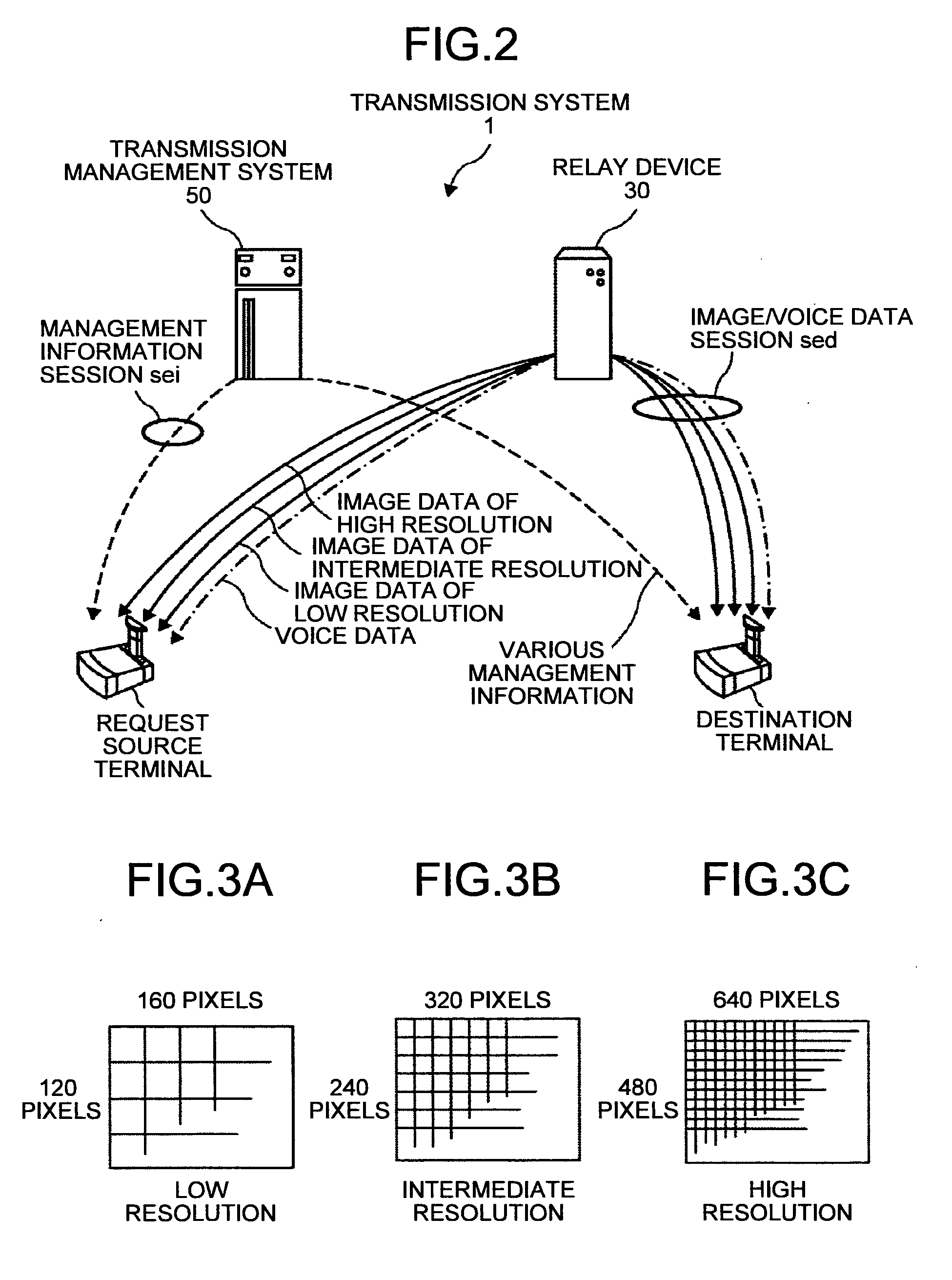
[0038]FIG. 1 is a schematic diagram of a transmission system 1 according to the present exemplary embodiment of the present invention. FIG. 2 is a conceptual diagram illustrating a transmission / reception state of image data, voice data, and a variety of management information in a transmission system. FIGS. 3A to 3C are conceptual diagrams for explaining the image quality of image data.

[0039]The transmission system includes a data providing system that transmits contents data in one direction from one transmission terminal to another transmission terminal through a transmission management system and a communication system that transmits information or a feeling between a plurality of transmission terminals through the transmission management system. The communication system refers to a system that transmits inf...

second embodiment

[0172]Hereinafter, a second exemplary embodiment of the present invention will be described with reference to FIG. 27. FIG. 27 is a sequence diagram illustrating a process of selecting the relay device at the terminal according to the second exemplary embodiment of the present invention. The present exemplary embodiment is different from the first exemplary embodiment in a process or operation in FIGS. 27 and 24, and thus a description will be made below in connection with the differences in a process or operation.

A Process or Operation of the Exemplary Embodiment

[0173]In step S61-1, step S62-1, step S61-2, and step S62-2 in FIG. 24 of the first exemplary embodiment, it is required that the management system 50 transmits the prior request information to the request source terminal (the terminal 10aa) through each of the relay devices 30a and 30b, whereas in the present exemplary embodiment, the management system 50 transmits the prior request information directly to the request sour...


PUM


Abstract

A transmission management system includes: a relay device management unit that manages relay device-specifying information for specifying each relay device on a communication network, for every piece of relay device-identification information for identifying each relay device; a terminal management unit that manages terminal-specifying information for specifying each transmission terminal on the communication network; a receiving unit that receives, from a transmission terminal as a predetermined request source, terminal-identification information for the request source and terminal-identification information for a transmission terminal as a destination; an extracting unit that extracts the terminal-specifying information of a corresponding transmission terminal based on the terminal-identification information for the request source; and a primary selecting unit that selects two or more pieces of relay device-identification information of relay devices, to which relay device-specifying information representing top two or more IP addresses closest to the IP address represented by the extracted terminal-specifying information, is allocated.

Description

TECHNICAL FIELD[0001]The present invention relates to a technique of selecting a relay device that actually relays contents data from among a plurality of replay devices capable of relaying contents data between a plurality of transmission terminals.BACKGROUND ART[0002]As an example of a transmission system in which contents data is transmitted or received between a plurality of transmission terminals through relay devices, there is a video conference system in which a video conference takes place via a communication network such as the Internet. Recently, the need for a video conference system is growing because of a tendency of saving expenses and time for business trips. In the video conference system, a plurality of video conference terminals are used as an example of the transmission terminals. The video conference can be made by reception and transmission of image data and voice data between the video conference terminals.[0003]Further, the recent enhancement of the broadband ...

Claims


Application Information

Patent Timeline
Patent Type & Authority Applications(United States)
IPC IPC(8): H04N7/14
CPCH04L12/1827H04N7/142H04N7/147H04N7/148H04L61/6068H04L65/403H04L67/1095H04L25/20H04L65/103H04L65/80H04L65/1066H04L2101/668H04L65/765H04L12/18H04N7/14H04N7/173
Inventor OKITA, KUNIOASAI, TAKAHIRO
Owner RICOH KK
Learn More