
Foldable Farm Implement

a technology of implements and frames, applied in the field of farm implements, can solve the problems of difficult to navigate corners that require a tight turning radius or around obstacles, difficult to maneuver the implement between crops along narrow roads, over bridges, through farm gates,

Inactive Publication Date: 2011-12-29
CNH IND AMERICA LLC
View PDF26 Cites 34 Cited by
  • Summary
  • Abstract
  • Description
  • Claims
  • Application Information

AI Technical Summary

Benefits of technology

The present invention is about a foldable frame for farm implements. The frame has several parts that can be folded up to make the implement easier to transport and store. The technical effect of this invention is to provide a compact arrangement for transport and stowage of the implement.

Problems solved by technology

The technical problem of this patent text is not specified and requires further analysis and interpretation.

Method used


Image

  • Foldable Farm Implement
  • Foldable Farm Implement
  • Foldable Farm Implement

Examples


Embodiment Construction

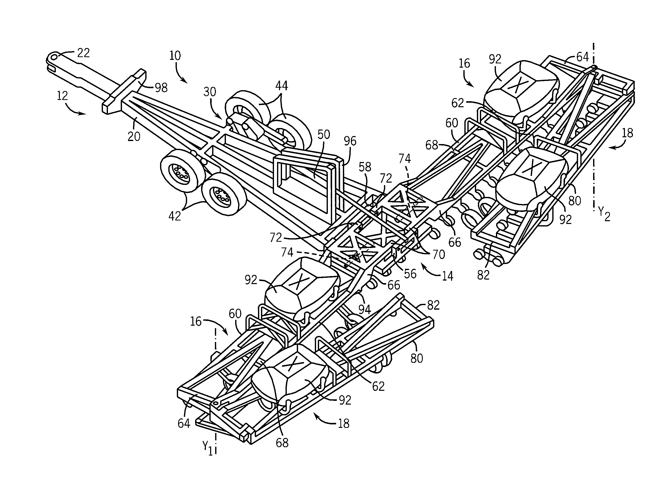
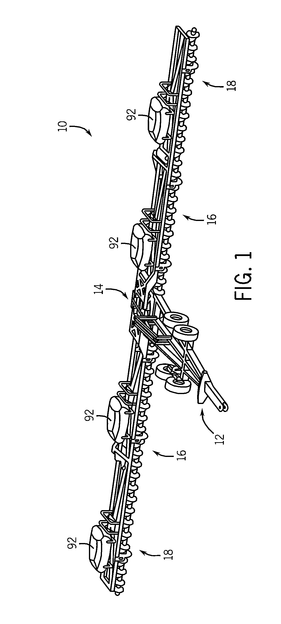
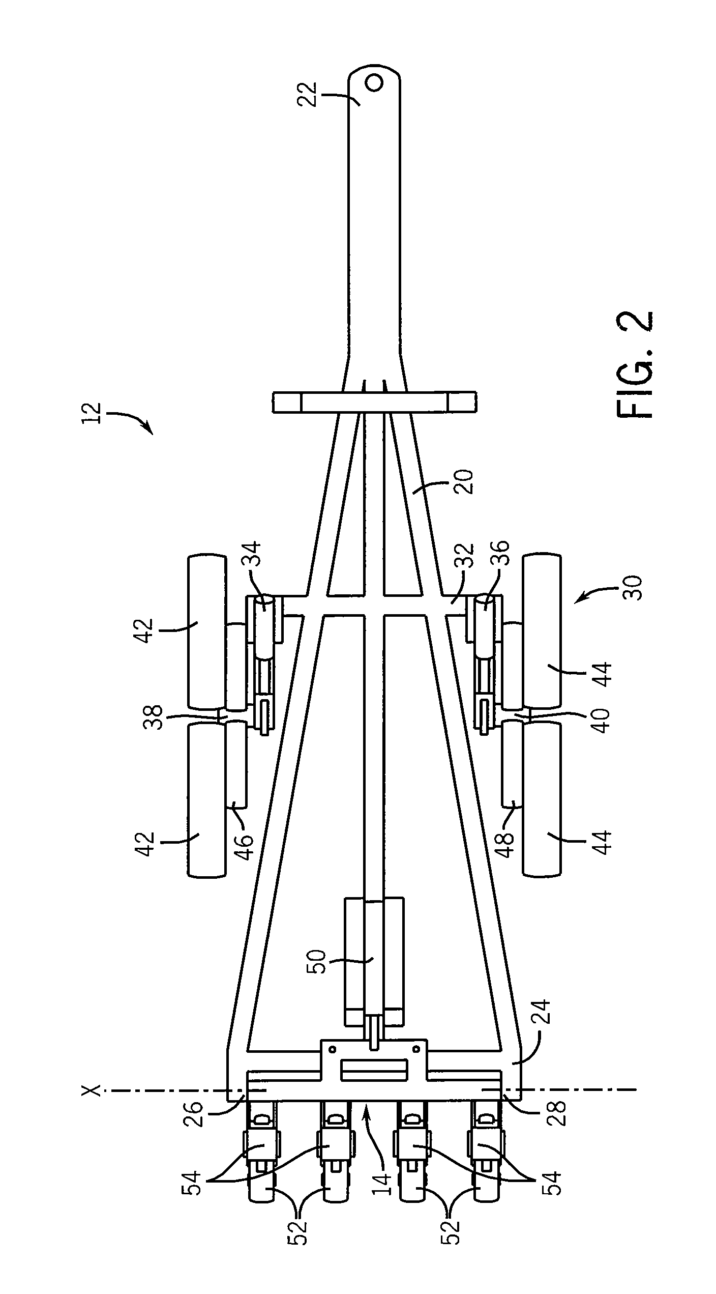
[0021]A foldable frame implement 10 according to one embodiment of the invention is shown in FIG. 1. The implement generally consists of a main frame assembly 12, a central frame member 14, inner wing members 16, and outer wing members 18. As will be described, several pivoting connections are used to interlink these components to allow the implement 10 to be folded from the extended in-field position shown in FIG. 1 to the folded, transport position shown in FIG. 6. While the foldable implement is not limited to any particular size, in one preferred embodiment, the implement has a width of 90 feet. In another embodiment, the implement has a width of 120 feet. In yet another embodiment, the implement has a width of 150 feet, and in a further embodiment, the implement has a width of 180 feet. It is also contemplated that the implement may have a width different from those listed above, including a width greater than 180 feet.

[0022]With additional reference to FIG. 2, the main frame a...


PUM


Abstract

A foldable implement frame is foldable about multiple axes to provide a compactly folded implement. The implement is foldable from a wide, field working position to a relatively narrow position for transport between fields, along roadways, and through field gates or storage doors. The frame is generally comprised of a center frame section that may be hitched to a prime mover, a pair of inner frame sections, and a pair of outer frame sections. The outer frame sections may be folded about their connections to the inner frame sections, and the inner frame sections are foldable about their connections to the central frame section. The central frame section may be rotated to rotate the inner and outer frame sections forward to an upright position, and the inner and outer frame sections may then be folded forward to fold the frame into a narrow position for transport and/or storage.

Description


Claims


Application Information

Patent Timeline
Owner CNH IND AMERICA LLC
Learn More