
Knee ligament testing device for measuring drawer and rotational laxity

a technology of rotational laxity and testing device, which is applied in the field of orthopaedic measuring devices, can solve the problems of inability to carry or measure the device, the subjectivity and dependence of the examiner's skill and expertise, and the inability to measure the devi

Inactive Publication Date: 2011-12-15
ARTHREX
View PDF9 Cites 11 Cited by
  • Summary
  • Abstract
  • Description
  • Claims
  • Application Information

AI Technical Summary

Benefits of technology

[0017]These and other features and advantages will be more apparent from the following detailed descript

Problems solved by technology

Injuries to the anterior cruciate ligament (ACL) or tendons, ligaments and joints in the knee can result in impaired movement or knee laxity and conditions such as osteoarthritis.
The disadvantages of physical examination are its subjectivity and dependence on the examiner's skill and expertise.
While some of these arthrometers can measure rotational knee laxity, these devices are either not portable or have certain limitations with respect to measurement.
By virtue of its design, the device allows, however, for measuring of only anterior-posterior knee laxity and cannot be employed to measure any other direction of force.

Method used


Image

  • Knee ligament testing device for measuring drawer and rotational laxity
  • Knee ligament testing device for measuring drawer and rotational laxity
  • Knee ligament testing device for measuring drawer and rotational laxity

Examples


Embodiment Construction

[0027]In the following detailed description, reference is made to the accompanying drawings which form a part hereof, and which illustrate specific embodiments. These embodiments are described in sufficient detail to enable those of ordinary skill in the art to make and use them. It is also understood that structural, logical, or procedural changes may be made to the specific embodiments disclosed herein.

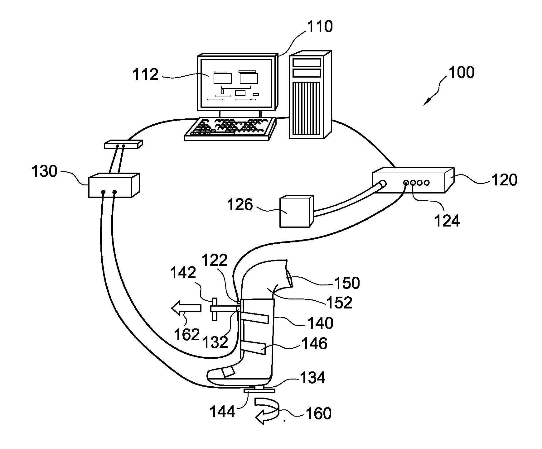
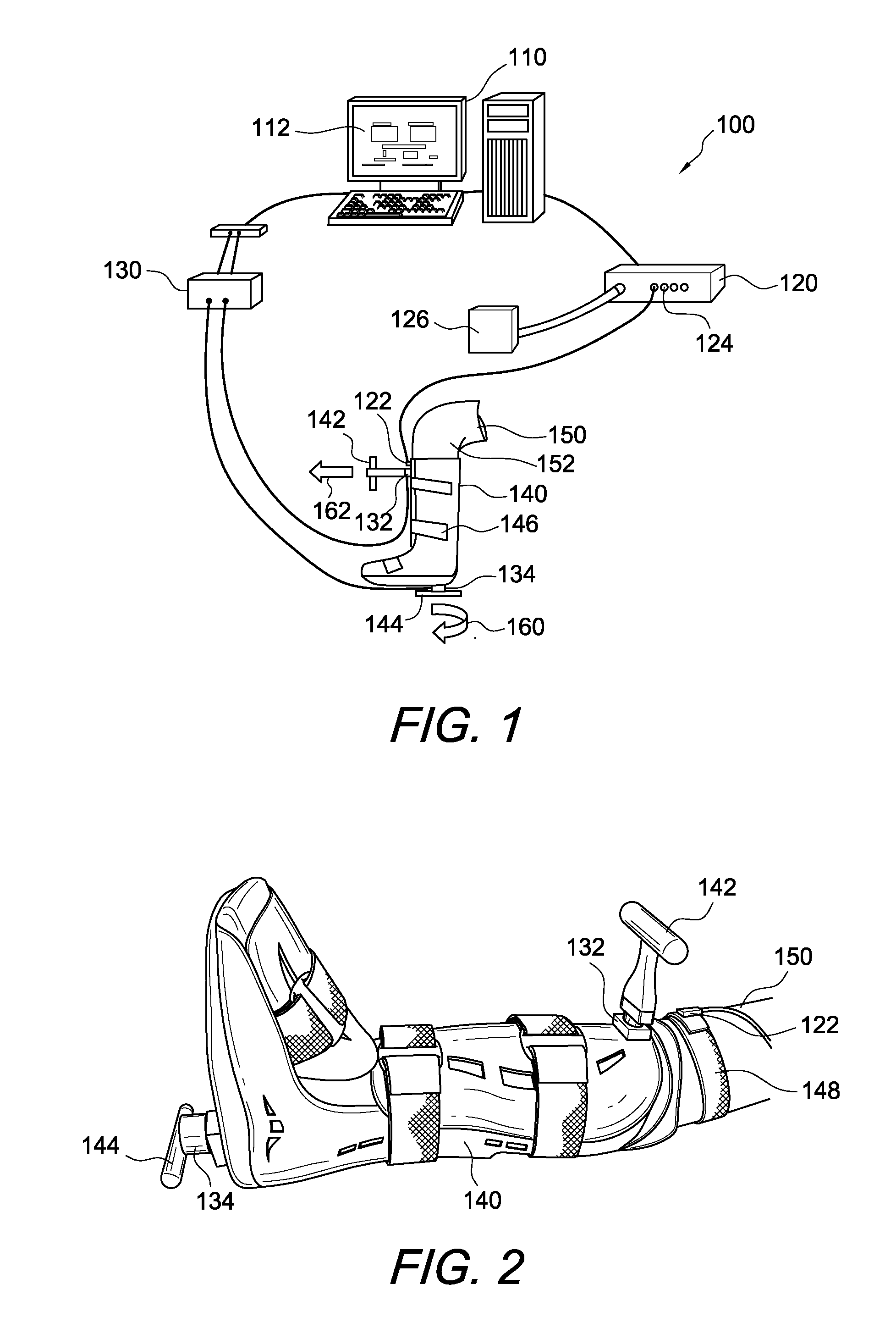
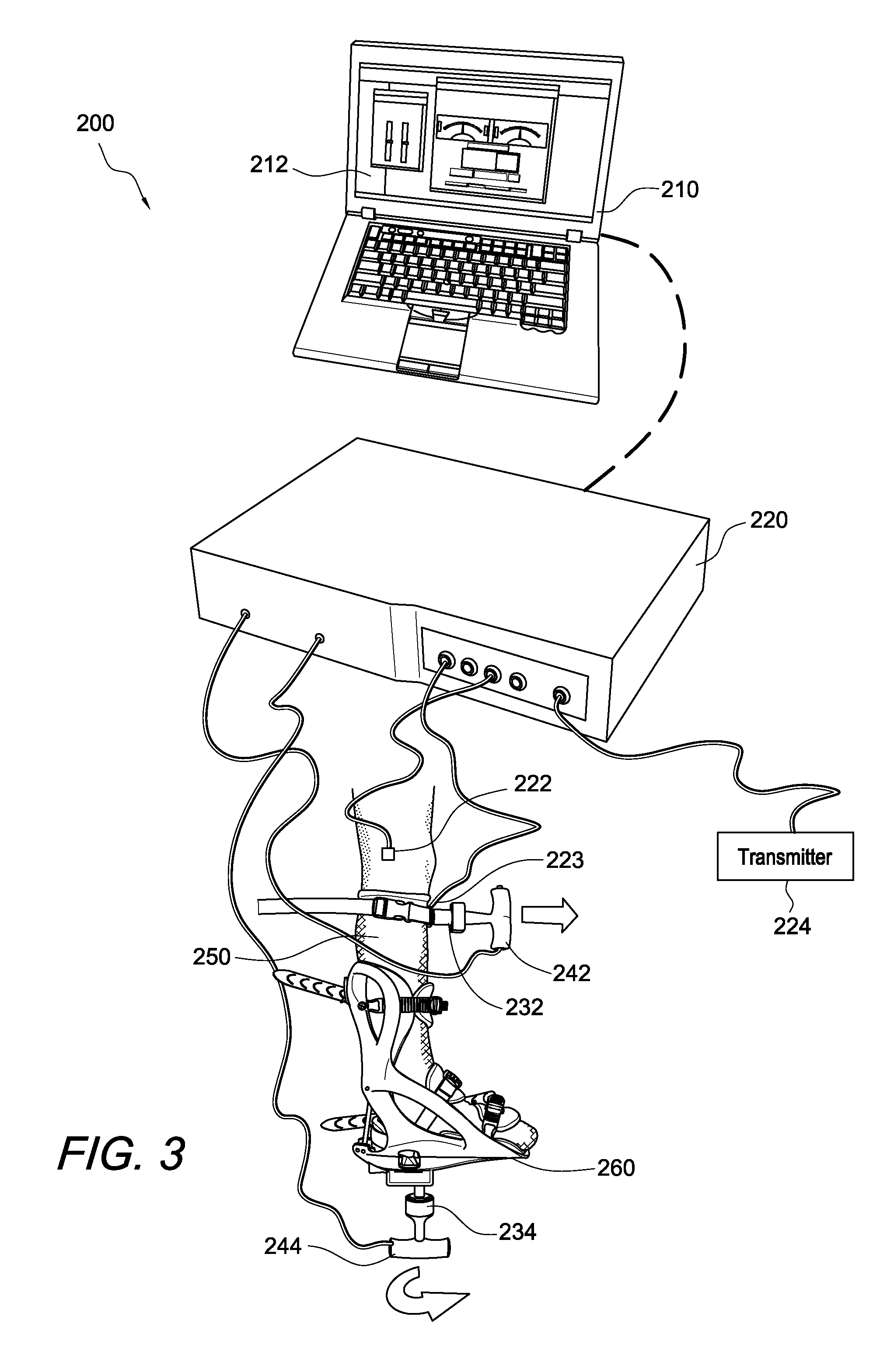
[0028]The system of the present invention can be used to measure both rotational laxity and posterior-anterior (i.e. drawer) laxity of a joint. The system uses various sensors to measure either the rotational and posterior-anterior laxity separately or at the same time.

[0029]An exemplary system 100 is depicted in FIG. 1. System 100 comprises a computer 110 with a display 112. Computer 110 has software that implements process 300 shown in FIG. 6. Display 112 is attached to computer 110 and is discussed further with regard to FIG. 7.

[0030]In system 100, computer 110 is in communicatio...


PUM


Abstract

A system and method for determining laxity in an anatomical joint. The system includes a force sensor that measures a force applied to an appendage that is coupled to a joint and a position sensor that determines the amount of movement of the appendage when the force is applied to the appendage. The system also includes a system controller that is connected to both the force sensor and the position sensor and allows communications between the sensors.

Description

CROSS REFERENCE TO RELATED APPLICATION[0001]This application claims priority to U.S. Provisional Application No. 61 / 354,060, filed on Jun. 11, 2010, the entire disclosure of which is incorporated by reference herein.FIELD OF THE INVENTION[0002]The present invention relates to orthopedic measuring devices and, more particularly, to a method and device for measuring anterior-posterior force and rotational torque in the knee.BACKGROUND OF THE INVENTION[0003]When joints or soft tissues such as tendons or ligaments are injured, testing is necessary to diagnose the extent of the injury, to determine proper treatment and to minimize future damage.[0004]Injuries to the anterior cruciate ligament (ACL) or tendons, ligaments and joints in the knee can result in impaired movement or knee laxity and conditions such as osteoarthritis. In general, there are two types of knee laxity, rotational knee laxity and anterior-posterior knee laxity. Rotational laxity occurs when the ligaments in the knee ...

Claims


Application Information

Patent Timeline
IPC IPC(8): A61B5/11
CPCA61B5/103A61B5/1121A61B5/6812A61B5/6831A61B5/6807A61B5/4528
Inventor CRABTREE, STEPHANIEKARNES, GREGORY JOSHUATIBONE, JAMES E.PEREZ, ARLEY
Owner ARTHREX
Learn More