
Trim attachment structure

a technology of attachment structure and tube, which is applied in the direction of fastening means, vehicle components, doors, etc., can solve the problems of adversely affecting the aesthetic appearance, and achieve the effects of reducing restrictions on the angular position of the tube (clip), improving aesthetic appeal, and increasing layout spa

Active Publication Date: 2011-12-08
AISIN SEIKI KK +1
View PDF20 Cites 53 Cited by
  • Summary
  • Abstract
  • Description
  • Claims
  • Application Information

AI Technical Summary

Benefits of technology

[0006]It is an object of the present invention to provide a garnish coupling structure that improves the aesthetic appearance while increasing the layout space.
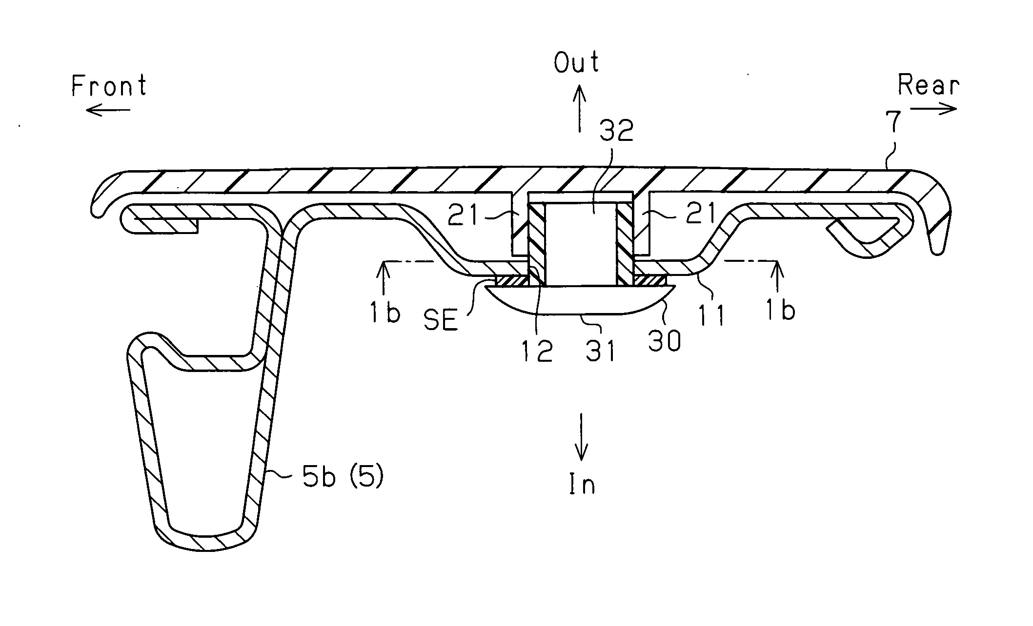
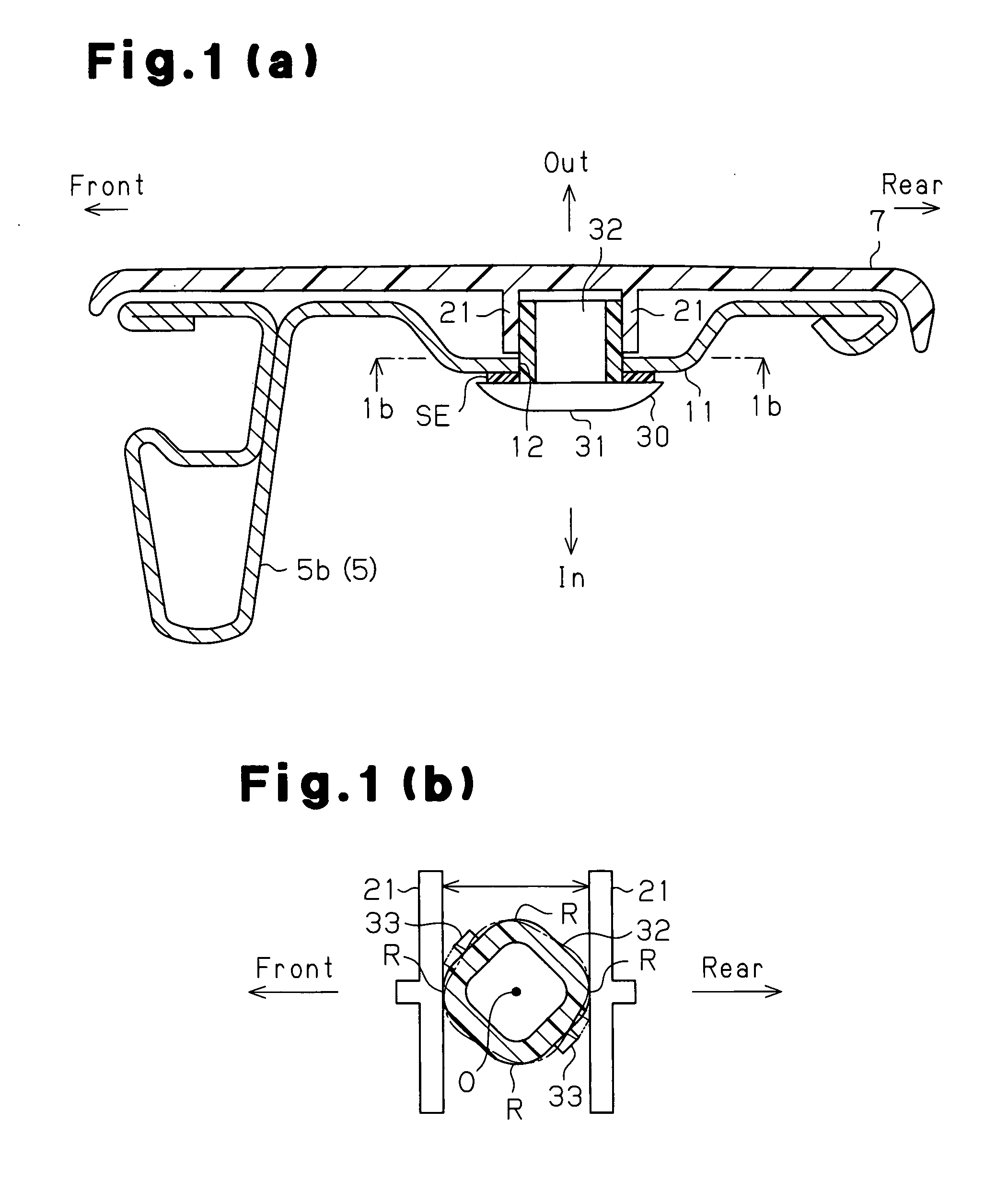
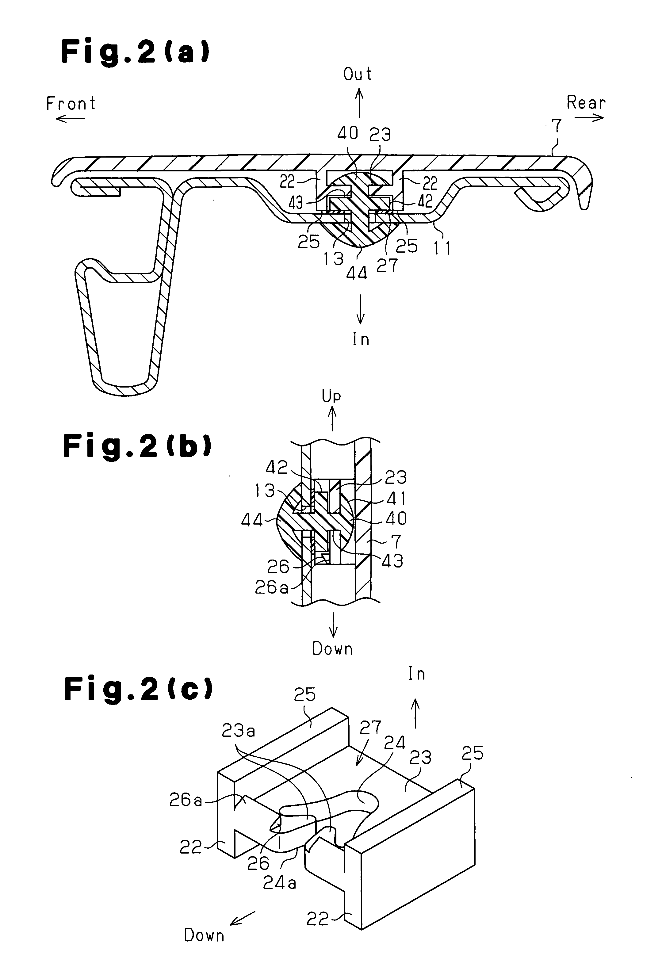
[0008]In this structure, the clip is engaged with the rim of the fitting hole at the outer side of the vehicle. This prevents separation of the clip from the fitting hole (coupling portion). The two ribs hold the two corners in the predetermined direction of the distal portion of the tube that project outward of the vehicle from the fitting hole to couple the garnish to the door frame with the clip. In this case, the head, which is bonded to the rim of the fitting hole toward the inner side of the vehicle, covers the fitting hole. Thus, the fitting hole and rust formed around the fitting hole are not exposed inward in the widthwise direction of the vehicle (inner side of the vehicle door 1). This improves the aesthetic appeal. Further, the head is bonded to the rim of the fitting hole in the coupling portion at the inner side of the vehicle. Thus, the projection length of the clip from the coupling portion inward in the vehicle is within the thickness range of the head. This prevents the layout space from being increased at the inner side of the vehicle. Further, the two ribs hold the two corners of the tube lying in the predetermined direction and are arranged so that the distance between the two is longest. Accordingly, the engagement hooks are arranged in the space formed between the two ribs and tube. Even when, for example, the engagement hooks are arranged on only some of the four side surfaces of the tube, interference between the engagement hooks and the two ribs does not occur as long as the tube is located at any one of angular positions located every 90 at which the tube can be fitted to the fitting hole. Accordingly, restrictions are reduced on the angular position of the tube (clip). This improves the coupling efficiency.

Problems solved by technology

This adversely affects the aesthetic appearance.

Method used


Image

  • Trim attachment structure
  • Trim attachment structure
  • Trim attachment structure

Examples


Embodiment Construction

[0022]FIG. 4 is a side view showing a garnish coupling structure according to one embodiment of the present invention applied to an upper portion of a vehicle door from an outer side of a vehicle in a widthwise direction.

[0023]As shown in FIG. 4, a vehicle door 1 includes a lower portion formed by a door body 2. The door body 2 is a hollow structural body obtained by joining an outer door panel, which forms an outer door plate, and an inner door panel (not shown), which forms an inner door plate. A door window glass DW, which moves into and out of an upper opening in the door body 2, is arranged in the door body 2.

[0024]The vehicle door 1 includes a door frame 5, which is arranged on a top portion of the door body 2. The door frame 5 forms a window sash, that is, a sash that holds the rim of the door window glass DW. The door frame 5 is molded to be tetragonal and is open in a downward direction. The door frame 5 includes a front frame portion 5a and rear frame portion 5b, which ext...


PUM


Abstract

A trim attachment structure includes a door frame, trim and a clip. The door frame has an attachment part, which is formed by a single plate, and a fitting hole. The fitting hole has a square shape in which the diagonals thereof are aligned with specific directions. The trim has a pair of ribs which extend towards the inner side in the width direction of the vehicle, respectively facing a pair of end parts of the fitting hole. The clip is installed in the fitting hole. The clip includes a head part, a tube part and a latching hook. The tube part has a tip end part which projects from the fitting hole to the outer side of the attachment part in the width direction of the vehicle. Angled parts of the tip end part are held between the ribs. The latching hook is latched at the peripheral edge of the fitting hole on the outer side of the attachment part in the width direction of the vehicle.

Description

BACKGROUND[0001]The present invention relates to a garnish coupling structure that couples a garnish, which covers a door frame forming a window sash of a vehicle door, to the door frame.[0002]Published Japanese application No. 2004-338522 discloses one example of a garnish coupling structure. FIG. 5 is a side view showing an upper portion of a vehicle door, to which such a garnish coupling structure of the prior art is applied, from an outer side of the vehicle in a widthwise direction. FIG. 6 is a cross-sectional view taken along line 6-6 in FIG. 5.[0003]FIG. 5 shows a door frame 91, which forms a window sash of a vehicle door. The door frame 91 includes a frame portion 92, which is located toward the rear of the vehicle. A garnish 93 covers the frame portion 92 from the outer side in the widthwise direction of the vehicle.[0004]The frame portion 92 is formed, for example, by roll-molding a metal plate that has a generally uniform cross-sectional shape in the longitudinal directio...

Claims


Application Information

Patent Timeline
IPC IPC(8): B60R13/04F16B2/20B60J5/04
CPCB60R13/04F16B5/065F16B21/088F16B21/086F16B5/0657
Inventor SAWATANI, SATOSHITSUBOKAWA, YUICHIOSETO, KEIGOKAWAKAMI, YASUAKIHASEGAWA, YASUTAKA
Owner AISIN SEIKI KK
Learn More