Cufflink Technology
a technology of cufflinks and cuffs, applied in the field of cufflinks and studs, can solve the problems of inadvertent actuation, deterioration of the ability of the locking mechanism to hold the halves together, and inability to meet the needs of wear and tear,
- Summary
- Abstract
- Description
- Claims
- Application Information
AI Technical Summary
Benefits of technology
Problems solved by technology
Method used
Image
Examples
first embodiment
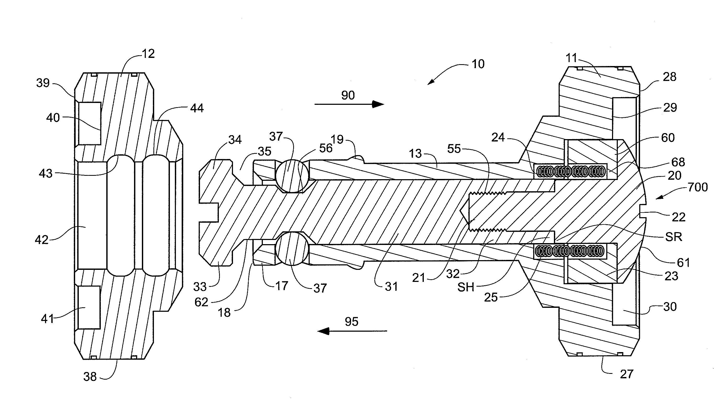
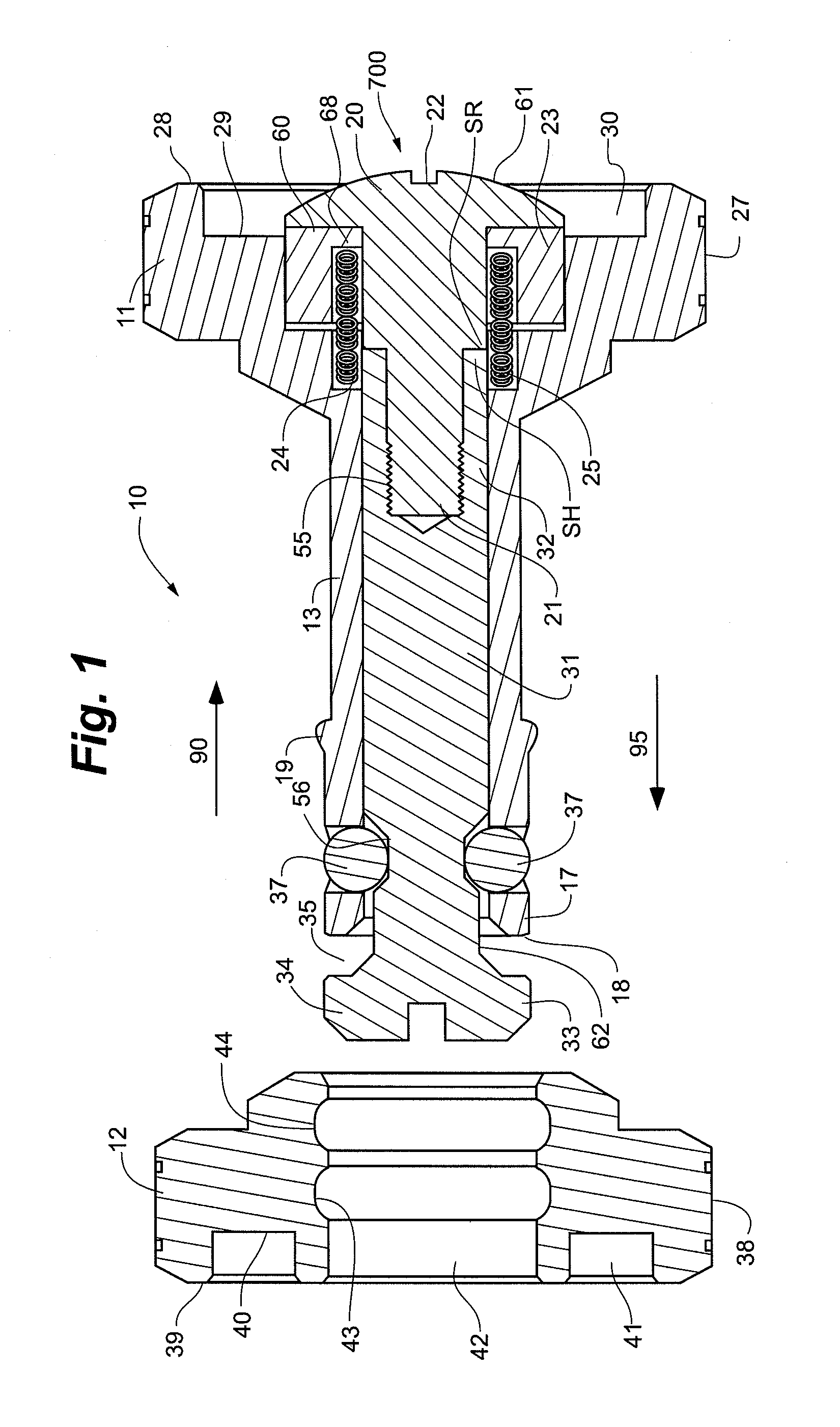
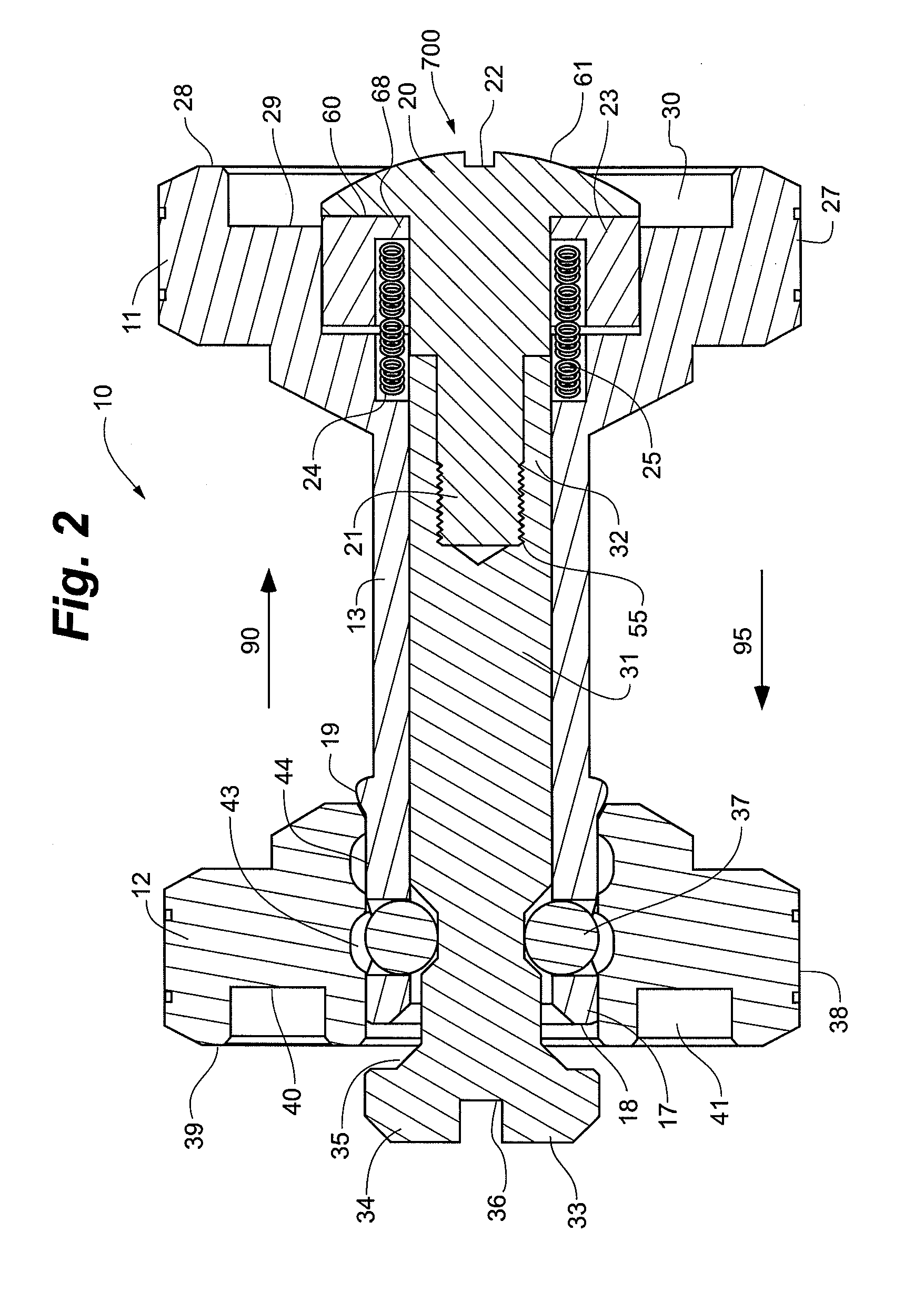
FIGS. 1-5 illustrate a cufflink 10 in accordance with a The cufflink 10 includes a first head 11 and a second head 12. These heads are opposed to one another (i.e., they are at opposite ends of the cufflink). The first 11 and second 12 heads can be placed in a separated (or “detached”) configuration, as shown in FIG. 1, or in a conjoined locked configuration, as shown in FIG. 3. In the embodiment illustrated, the first 11 and second 12 heads can be locked selectively in either a first locked position or a second locked position. Moreover, the cufflink can optionally be configured so as to have three or more locked positions. More will be said later of the optional adjustability feature.
In the embodiment of FIGS. 1-5, a shaft 13 projects from the first head 11 of the cufflink. In some cases, the first head 11 and the shaft 13 are defined by a single integral body, although this is not strictly required. The shaft 13 extends from the first head 11 to a distal end region 17. The illus...
second embodiment
FIGS. 6-10 illustrate a cufflink 110 in accordance with a Here again, the cufflink 110 includes a first head 111 and a second head 112. These two heads are opposed to each other (i.e., they are at opposite ends of the cufflink). The two heads 111, 112 can be placed in a separated (or “detached”) configuration, as shown in FIG. 6, or in a conjoined locked configuration, as shown in FIG. 8. A first neck region 113 projects from the first head 111 to a mateable distal end region 114. In some embodiments, the first head 111, first neck region 113, and first distal end region 114 are all defined by a single integral body. However, this is not required.
The illustrated cufflink 110 includes an actuator 1700 comprising a plunger 131. The plunger 131 has a proximal end region 132 and a distal end region 133. The proximal end region 132 of the illustrated plunger 131 includes an interiorly threaded opening 155. The actuator 1700 comprises a manually operable control 120 that is accessible fo...
third embodiment
FIGS. 11-14 illustrate a stud 210 in accordance with a The stud 210 includes a first head 211, second head 212, and central neck region 213. The two heads are at opposite sides of the stud and the neck extends between them (i.e., the neck connects the two heads). Here, the heads are enlarged and the neck is relatively narrow (e.g., has a relatively small diameter, as compared to the heads). In some cases, the first head 211, second head 212, and neck region 213 are defined by a single integral body. Alternatively, the stud can comprise two halves joined together to form the same general configuration as that shown. In still other embodiments, the stud can comprise three or more bodies joined together so as to define the two heads and the neck. Many variants of this nature will be apparent given the present teaching as a guide.
The first head 211 has (e.g., defines) a pocket 255 configured to receive a removable decorative insert 249. The illustrated pocket 255 has a larger diameter ...
PUM
 Abstract
Description
Claims
Application Information
 - R&D
- Intellectual Property
- Life Sciences
- Materials
- Tech Scout
- Unparalleled Data Quality
- Higher Quality Content
- 60% Fewer Hallucinations
Browse by: Latest US Patents, China's latest patents, Technical Efficacy Thesaurus, Application Domain, Technology Topic, Popular Technical Reports.
© 2025 PatSnap. All rights reserved.Legal|Privacy policy|Modern Slavery Act Transparency Statement|Sitemap|About US| Contact US: help@patsnap.com


