
Resonance modifying connector

Active Publication Date: 2011-11-03
MOLEX INC
View PDF9 Cites 39 Cited by
  • Summary
  • Abstract
  • Description
  • Claims
  • Application Information

AI Technical Summary

Benefits of technology

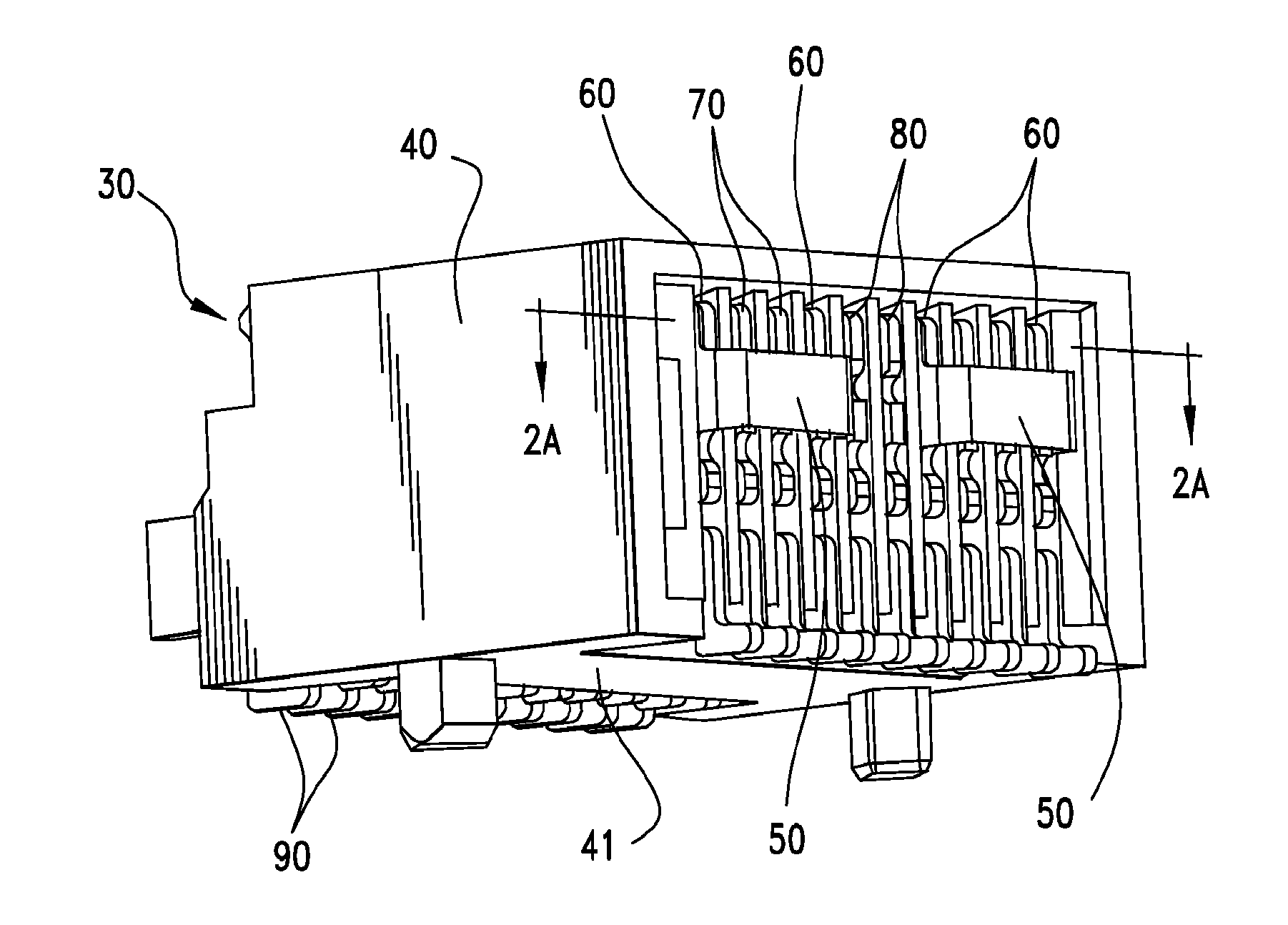
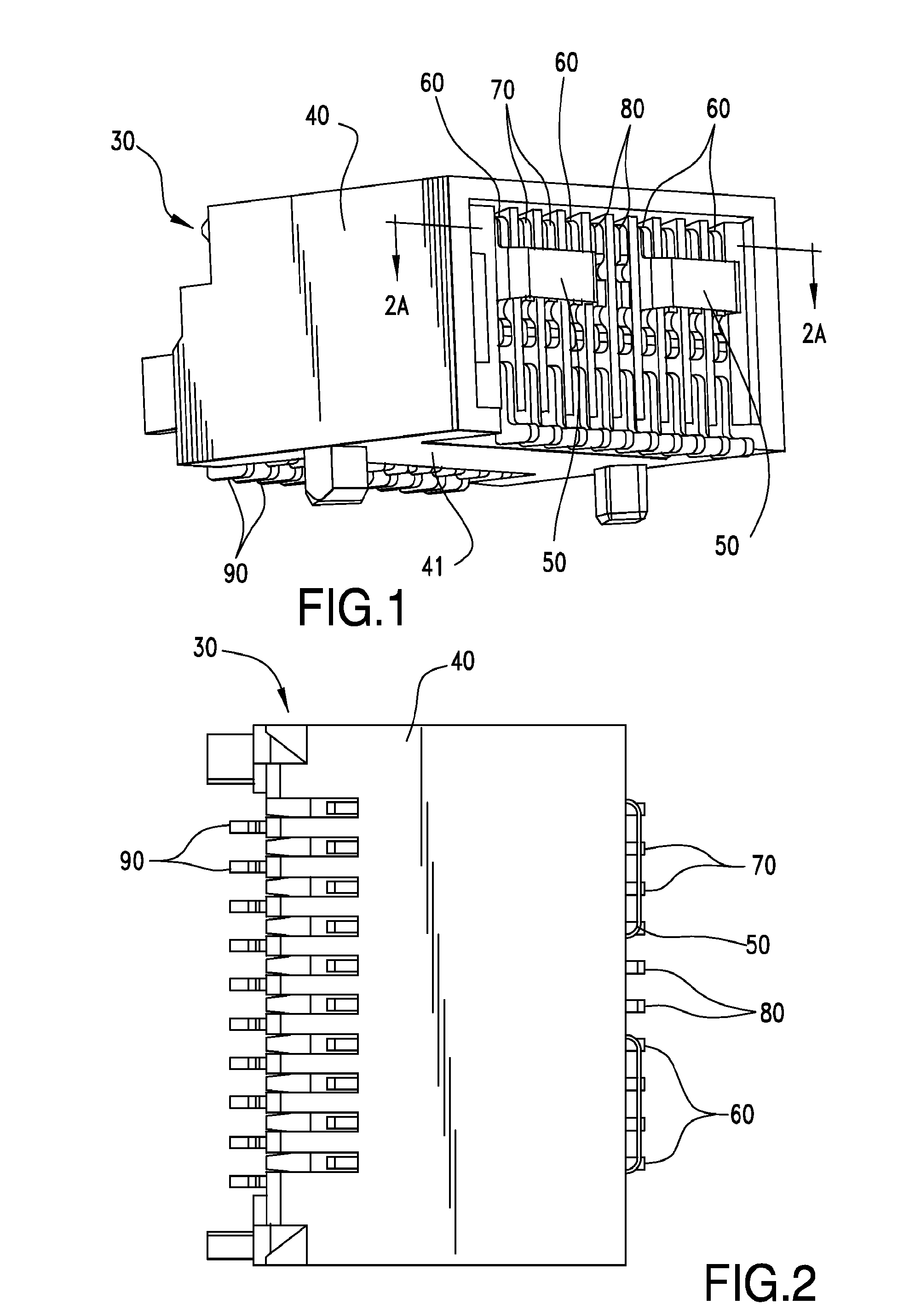
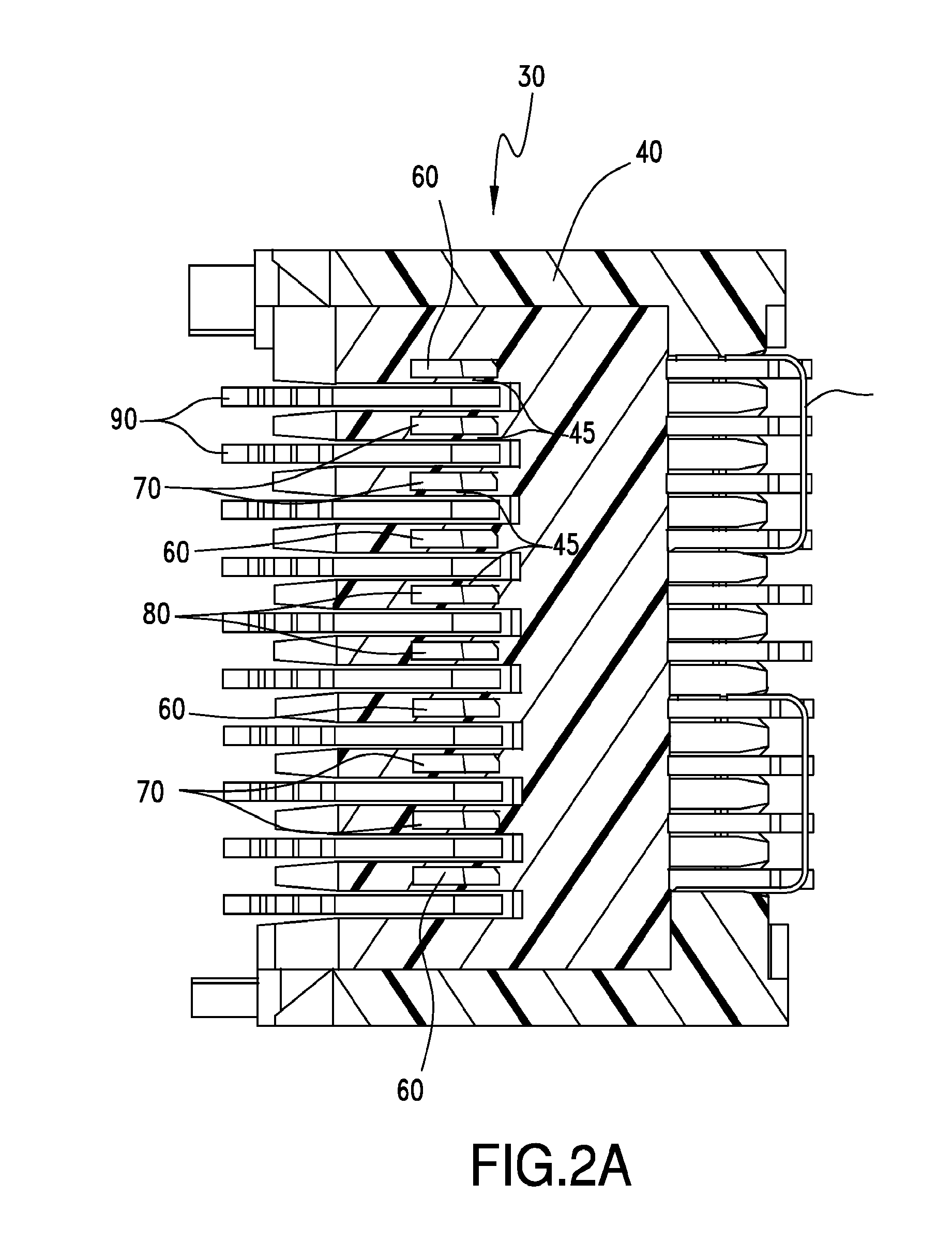
[0005]A connector includes a plurality of ground and signal terminals, creating a complex transmission structure. The resultant resonant frequency of two ground terminals may be modified by coupling the two ground terminals together with a bridge so as to provide predetermined maximum electrical length associated with a particular resonance frequency. In an embodiment, two ground terminals may be coupled together via a bridge that extends transversely to a differential si

Problems solved by technology

One issue that has begun to be noticed with increased importance is that as the frequency of the signals increases (so as to increase the effective data communication speeds), the electrical and physical length of the connector becomes more of a factor.
Thus, even connectors systems configured to use differential signal pairs begin to have problems as the frequency increases.
Consequentially, the potential resonance condition in existing connectors tends to make them difficult or unsuitable for use in higher speed applications.

Method used


Image

  • Resonance modifying connector
  • Resonance modifying connector
  • Resonance modifying connector

Examples


Embodiment Construction

[0024]As required, detailed embodiments are disclosed herein; however, it is to be understood that the disclosed embodiments are merely exemplary and the depicted features may be embodied in various forms. Therefore, specific details disclosed herein are not to be interpreted as limiting, but merely as a basis for the claims and as a representative basis for teaching one skilled in the art to variously employ the disclosed features in virtually any appropriate manner, including employing various features disclosed herein in combinations that might not be explicitly described.

[0025]Small form pluggable (SFP) style connectors are often used in systems where an input / output (I / O) data communication channel is desired. It should be noted that used herein, the phrase SFP style connector refers generically to connector that can similar functionality to what is provided by a SFP standard based connector, however it is not so limited but instead refers to the general construction and thus i...


PUM


Abstract

A connector assembly is provided that is suitable for controlling the resonance frequency of ground terminals used to shield high-speed differential pairs. Ground terminals may be commonized so as to provide ground terminals with a predetermined maximum electrical length. Reducing the electrical length of the ground terminal can move a resonance frequency of the ground terminals of the connector outside the range of frequencies at which signals will transmitted.

Description

[0001]This application is a national phase of PCT Application No. PCT / US09 / 64300, filed Nov. 13, 2009, which in turn claims priority to U.S. Provisional Ser. Application No. 61 / 114, 897, filed Nov. 14, 2008, both of which are incorporated herein by reference in their entirety.BACKGROUND OF THE INVENTION[0002]The present invention generally relates to connectors suitable for high-speed communication.[0003]While a number of different configurations exist for high-speed connectors, one common configuration is to align a number of terminals in a row so that each terminal is parallel to the adjacent terminal. It is also common for such terminals to be closely spaced together, such as at a 0.8 mm pitch. Thus, high-speed connectors tend to include a number of tightly spaced and similarly aligned terminals.[0004]High-speed communication channels tend to use one of two methods, differential signals or single-ended signals. In general, differential signals have a greater resistance to interfe...

Claims


Application Information

Patent Timeline
IPC IPC(8): H01R24/00
CPCH01R29/00H01R31/08H01R13/6585H01R13/6474H01R13/6471
Inventor CASHER, PATRICK R.REGNIER, KENT E.
Owner MOLEX INC
Learn More