
Parallel-connected resonant converter circuit and controlling method thereof

a resonant converter and parallel connection technology, applied in the direction of electric variable regulation, process and machine control, instruments, etc., can solve the problems of large co, large volume of output filter, and high power loss

Active Publication Date: 2011-11-03
DELTA ELECTRONICS INC
View PDF4 Cites 23 Cited by
  • Summary
  • Abstract
  • Description
  • Claims
  • Application Information

AI Technical Summary

Benefits of technology

The present invention provides a parallel-connected resonant DC / DC converter circuit and a controlling method that can achieve current balance among converters when the switching frequencies of all converters are the same. The circuit includes a plurality of resonant converters that are connected in parallel with each other, and each other through input and output terminals. The circuit can operate under an interleaved mode and at substantially the same frequency. The technical effect of the invention is to achieve a more stable and balanced current distribution among the converters, leading to improved performance and efficiency of the parallel-connected resonant converter circuit.

Problems solved by technology

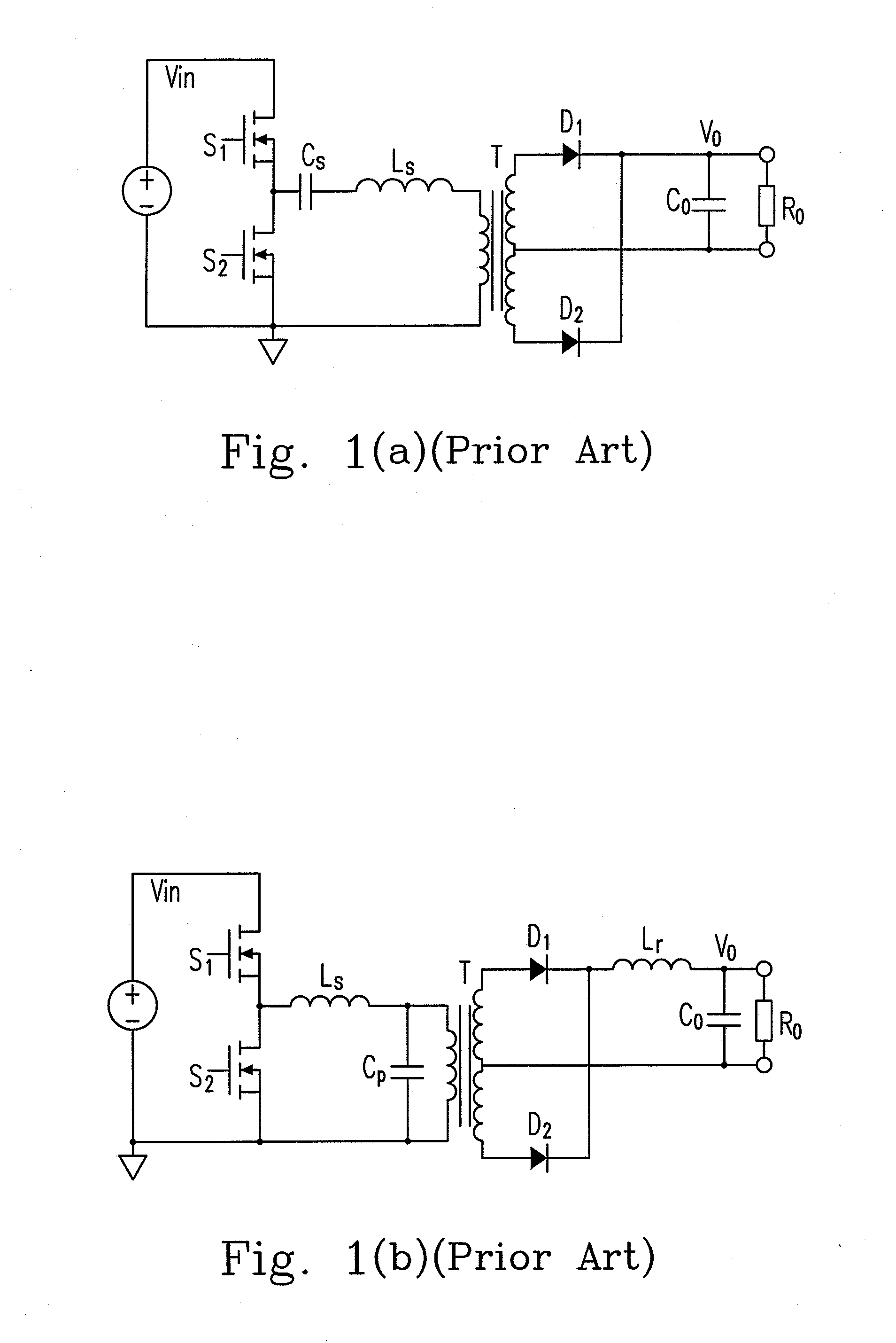
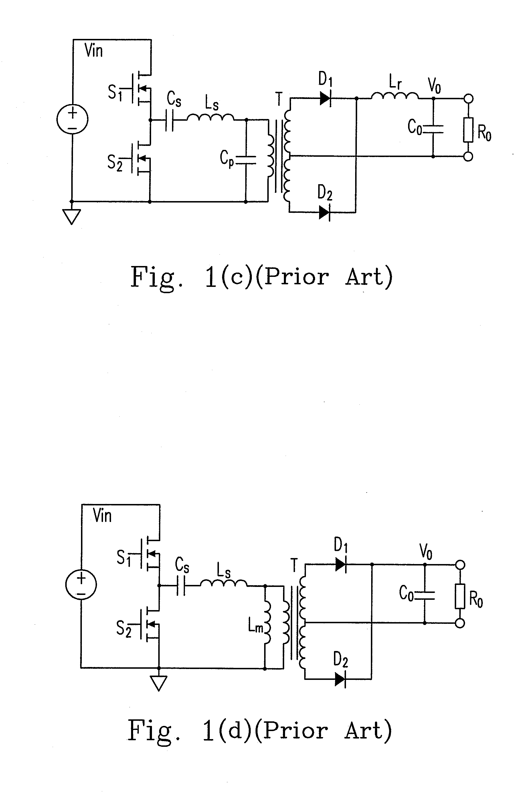
However, there are still certain existing drawbacks regarding the resonant DC / DC converter, e.g., the high ac current of the output filter of the series resonant DC / DC converter resulting in the high power loss and the large volume of the output filter.
And since iD1 and iD2 have larger ripples, the ac current value of the output filter (output capacitor) Co is large which results in large size of Co and high power loss of the converter.
However, some problems still exist due to the characteristics of the resonant converters.
If the resonant converters are forced to operate in the same frequency, the current balance between the interleaved resonant converters is hard to be realized due to their different characteristics.

Method used


Image

  • Parallel-connected resonant converter circuit and controlling method thereof
  • Parallel-connected resonant converter circuit and controlling method thereof
  • Parallel-connected resonant converter circuit and controlling method thereof

Examples


Embodiment Construction

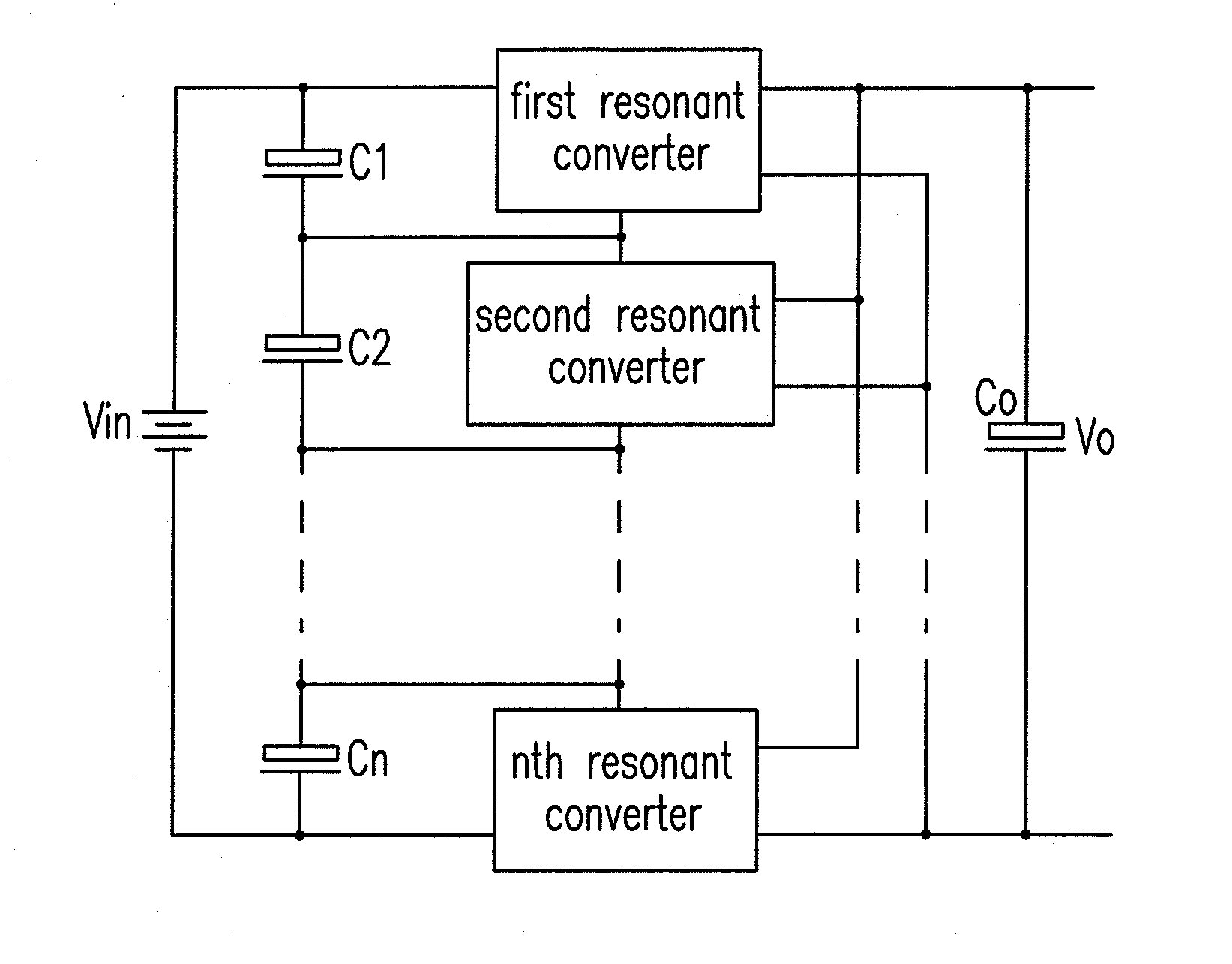
[0036]As shown in FIG. 3, it is a schematic circuit diagram of a circuit having N parallel-connected resonant converters operating in interleaved mode according to the first preferred embodiment of the present invention. In which, it includes a DC power source, input capacitors C1-Cn, a first to a nth resonant converters and an output capacitor Co providing an output voltage. All the DC inputs of the DC / DC resonant converters are series-connected, all the outputs of the DC / DC resonant converters are parallel-connected, and the switching frequencies of all the converters are substantially the same.

[0037]Taking the example of two parallel-connected resonant converters as shown in FIG. 4, it includes a DC power source Vin, a first and a second resonant converters, a first and a second input capacitors C1-C2, and an output capacitor Co providing an output voltage Vo.

[0038]Vin1 and Vin2 indicate the input voltages of the first and the second resonant converters respectively; Iin1 and Iin...


PUM


Abstract

The configurations of a parallel-connected resonant converter circuit and a controlling method thereof are provided in the present invention. The proposed circuit includes a plurality of resonant converters, each of which has two input terminals and two output terminals, wherein all the two input terminals of the plurality of resonant converters are electrically series-connected, and all the two output terminals of the plurality of resonant converters are electrically parallel-connected.

Description

CROSS REFERENCE TO RELATED APPLICATIONS[0001]This application is a continuation of U.S. patent application Ser. No. 12 / 394,571 filed on Feb. 27, 2009; the entirety of which is incorporated herein by reference.FIELD OF THE INVENTION[0002]The present invention relates to a parallel-connected resonant DC / DC converter circuit and a controlling method thereof, which can be employed to realize a current balance among converters when the switching frequencies of all the converters are the same.BACKGROUND OF THE INVENTION[0003]The developing trend of the DC / DC converter is just like that of the most of the power supply products, that is—high efficiency. The resonant DC / DC converter is easier to realize the high efficiency due to its feature of soft-switching. However, there are still certain existing drawbacks regarding the resonant DC / DC converter, e.g., the high ac current of the output filter of the series resonant DC / DC converter resulting in the high power loss and the large volume of ...

Claims


Application Information

Patent Timeline
Patent Type & Authority Applications(United States)
IPC IPC(8): H02M3/335
CPCH02M3/33569Y02B70/1433H02M2001/0074Y02B70/10Y02P80/10H02M1/0074H02M3/33571H02M3/01
Inventor YE, HAOYIZENG, JIANHONGWU, HONGYANGYAN, CHAOLIU, TENGYING, JIANPING
Owner DELTA ELECTRONICS INC
Learn More