
Ventilation System With System Status Display For Configuration And Program Information

a technology of program information and display system, which is applied in the direction of operating means/releasing devices of valves, local control/monitoring, instruments, etc., can solve the problems of excessive power consumption, unattractive use of battery-powered devices, and excessive power consumption of display displays

Active Publication Date: 2011-10-27
TYCO HEALTHCARE GRP LP
View PDF0 Cites 137 Cited by
  • Summary
  • Abstract
  • Description
  • Claims
  • Application Information

AI Technical Summary

Benefits of technology

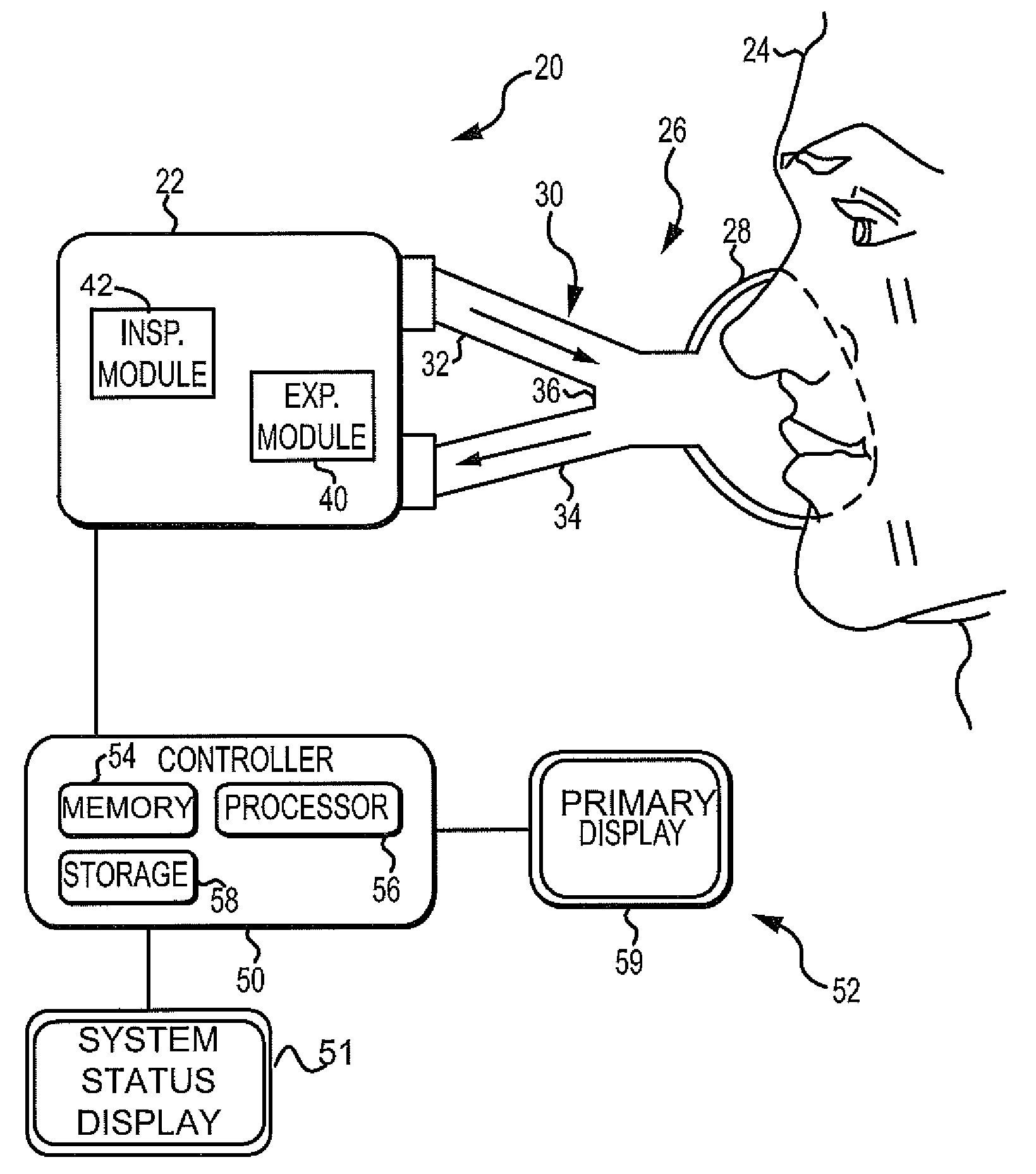
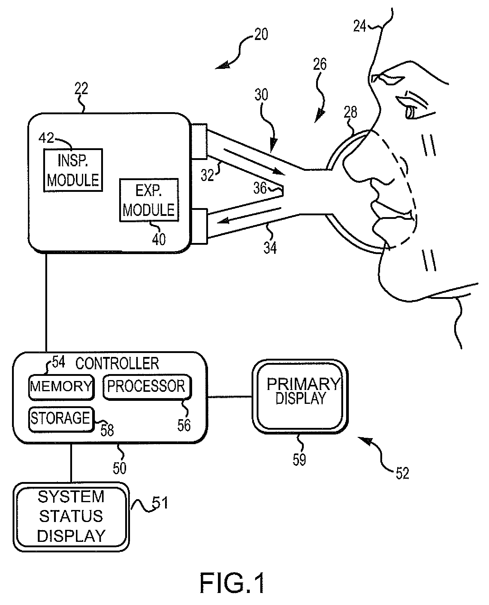
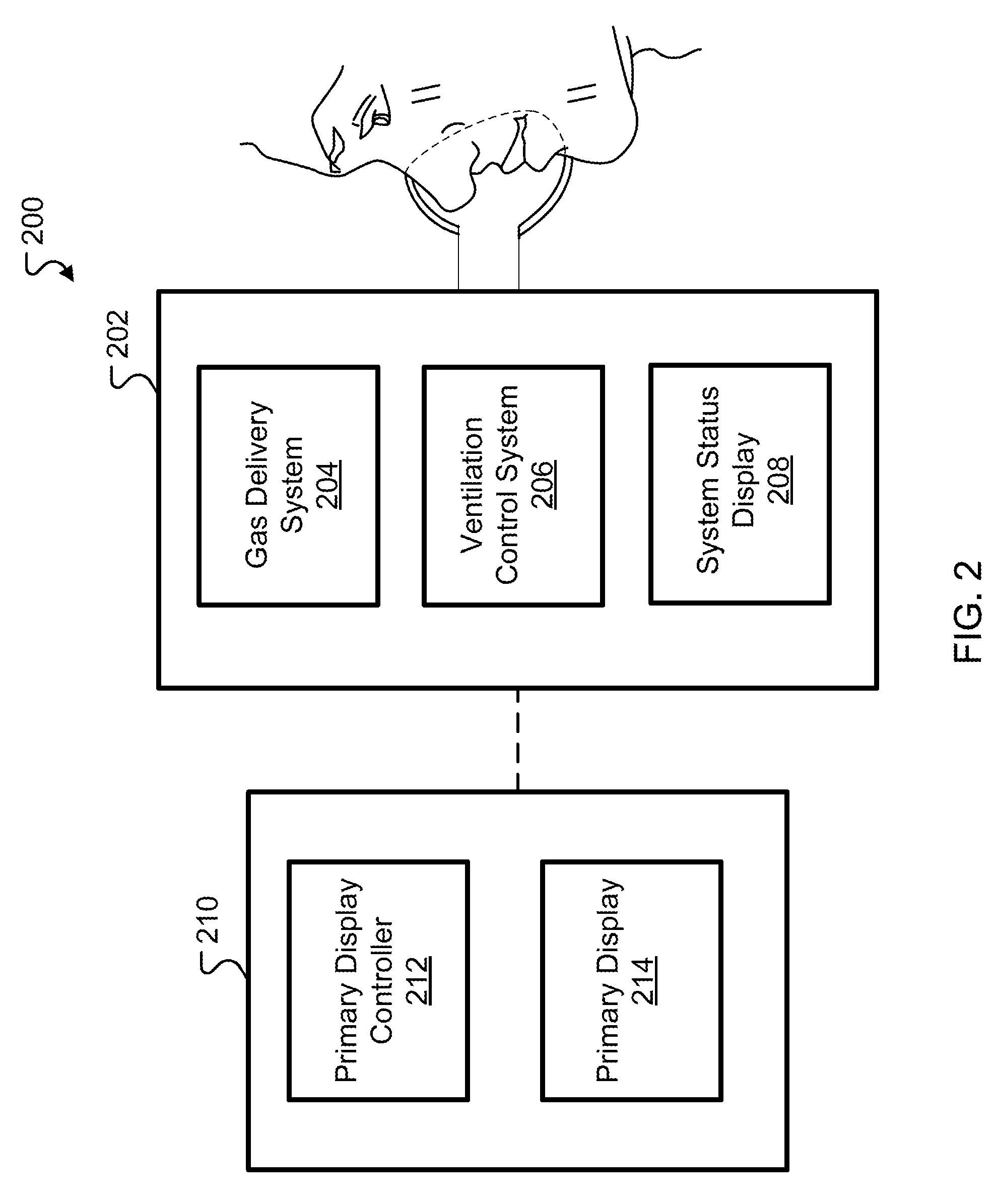
[0019]Yet another aspect of this disclosure describes a ventilation system that includes: a main housing; a gas delivery system in the main housing; a ventilation control system in the main housing that controls the gas delivery system and monitors one or more of a patient physiological parameter, operational parameters of the ventilation system and user-defined parameters; a primary display controller that generates a graphical user interface and that receives user inputs through the graphical user interface and del

Problems solved by technology

A drawback of electronic GUIs is the power consumption the displays require.
Large and high resolution displays and support circuitry often consume excessive amounts of power, making them unattractive for use with battery-powered devices.
Yet another drawback related to the power consumption issue is that in order for an operator to interact with or obtain information from the device in any way, the electronic GUI must be powered on, even when the information needed is unrelated to the operation of the device.
However, such ancillary user interface elements can not be reconfigured as they are built into their devices.
Another drawback to currently utilized ventilator systems is that different ventilators are often configured differently, making it difficult for ventilator operators to quickly find and / or locate the physical components of the ventilator.
Current systems provide stickers or papers on the ventilator system to direct the operator to proper parts in an attempt to help alleviate this problem; however, these stickers and papers may fade or fall off the ventilator over time.
An additional drawback to currently utilized ventilator systems is that the increased specificity and wide variety of ventilator systems and programs makes it difficult for a ventilator operator to quickly choose a desired and / or proper ventilator.
The ventilator operator may have a limited amount of time to determine if a ventilator provides the needed features, contains enough of the desired gas source, and / or is properly configured, charged, maintained, and / or serviced.
Because ventilators are typically utilized in complicated environments, such as in intensive care units, the operator may have a limited amount of time to pick and completely understand a ventilator.
The large number of differences between different ventilators increases the amount of time necessary for an operator to pick and completely understand a ventilator, which is an undesirable side-effect of ventilator variety and specialization.

Method used


Image

  • Ventilation System With System Status Display For Configuration And Program Information
  • Ventilation System With System Status Display For Configuration And Program Information
  • Ventilation System With System Status Display For Configuration And Program Information

Examples


examples

[0152]The following are embodiments of displays that could be shown on the SSD of a ventilation system.

[0153]The following are embodiments of a pressure trace or manometer that could be displayed on a SSD to allow an operator to determine from the SSD the ventilator's ability to support breath delivery to a patient.

[0154]FIGS. 8 and 9 illustrate an embodiment of a screen shot of a display on a ventilation system 800. In this example, the SSD displays a pressure trace or manometer 802 that indicates that pressure is transitioning between two points, such as PEEP and Peak Inspiratory Pressure (PPEAK). As illustrated in FIGS. 8 and 9, the SSD displays a pressure trace 802 that provides an indication of the rise time of the pressure and the pressure levels. Further, as shown in the FIGS. 8 and 9, the SSD provides a continuous display of the minimum and peak inspiratory pressure levels.

[0155]As illustrated in FIGS. 8 and 9, the manometer 802 includes high and low peak inspiratory pressur...


PUM


Abstract

The disclosure describes a novel approach for displaying information on a ventilation system. The disclosure describes a novel respiratory system including a removable primary display and system status display. Further, the disclosure describes a novel method for displaying ventilator information and a novel method for controlling a ventilation system.

Description

INTRODUCTION[0001]Many devices now use electronic graphical user interfaces (GUIs) as the primary user interface means instead of panels with mechanical elements such as knobs, buttons, switches etc. These GUIs are typically presented on a suitably-sized display (such as a flat panel display) in conjunction with a pointing or, as is increasingly common, a touch-sensitive display.[0002]A drawback of electronic GUIs is the power consumption the displays require. Large and high resolution displays and support circuitry often consume excessive amounts of power, making them unattractive for use with battery-powered devices.[0003]Yet another drawback related to the power consumption issue is that in order for an operator to interact with or obtain information from the device in any way, the electronic GUI must be powered on, even when the information needed is unrelated to the operation of the device. For example, a device may have a battery that can be charged from wall power when the de...

Claims


Application Information

Patent Timeline
IPC IPC(8): A61M16/00
CPCA61M16/00A61M16/16A61M2205/18A61M2205/505G06F19/3481A61M2205/8237A61M2209/086G06F19/3406A61M2205/8206A61M16/0051A61M16/0063A61M16/024G16H20/40G16H40/63
Inventor SANCHEZ, GABRIELHYDE, DAVIDCLEVELAND, DONNALEONE, KENNETH
Owner TYCO HEALTHCARE GRP LP
Learn More