
Display system and device with sustainable power generation

a technology of display system and power generation, applied in the field of display system and device, can solve the problems of large energy consumption, upset tenants, and typically not available side of buildings for advertising,

Active Publication Date: 2011-10-20
GREEN DISPLAY
View PDF8 Cites 21 Cited by
  • Summary
  • Abstract
  • Description
  • Claims
  • Application Information

AI Technical Summary

Benefits of technology

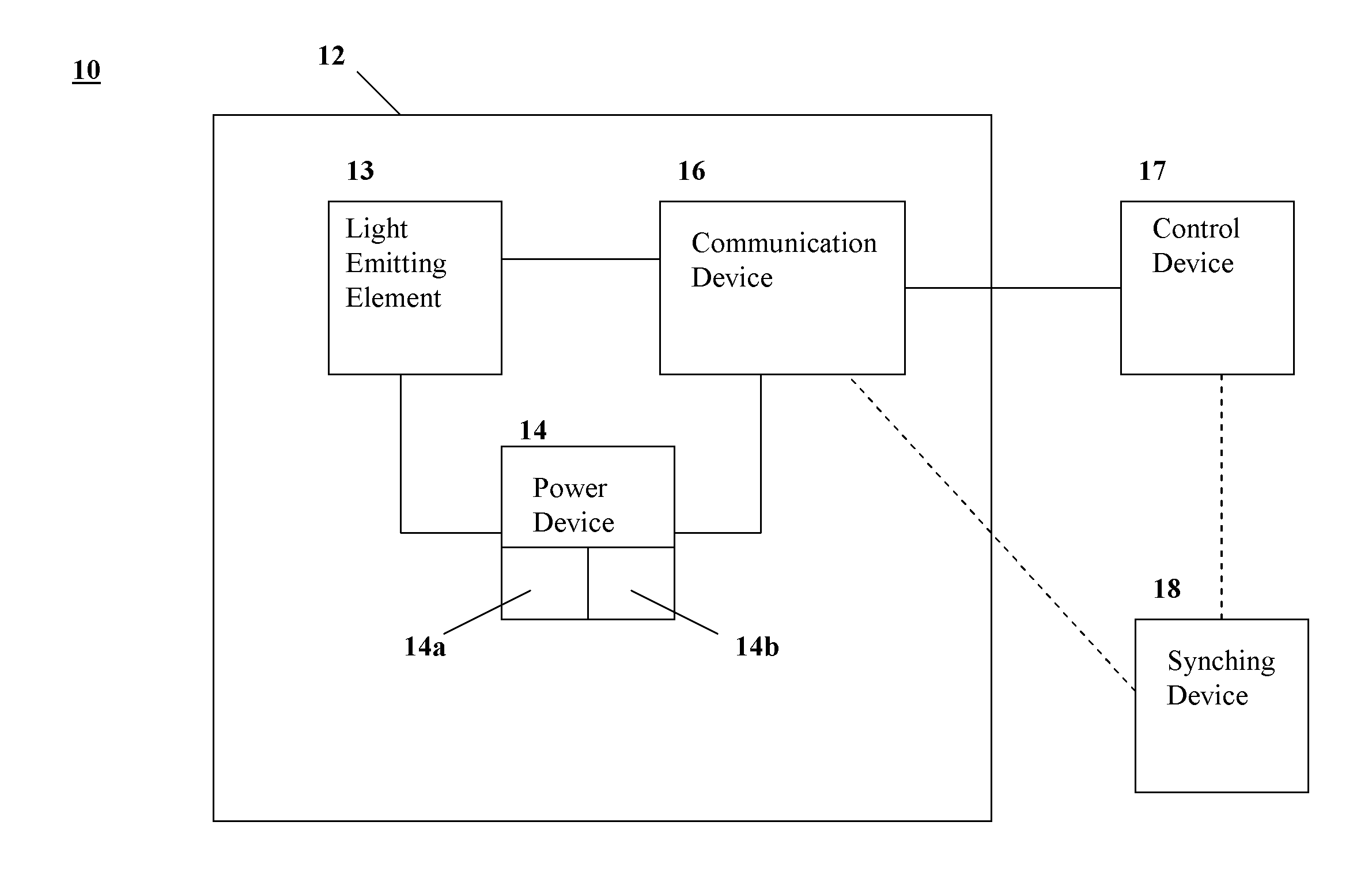
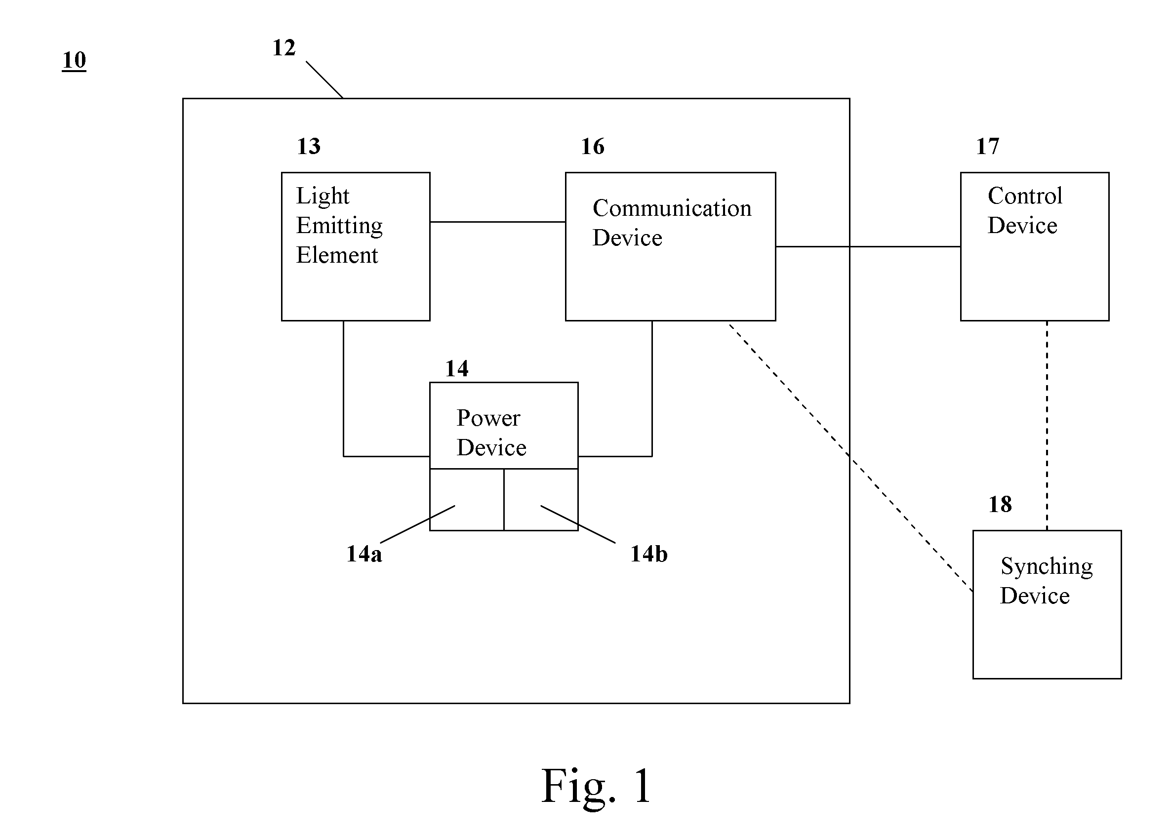
"The present invention provides a display system and device that can be mounted on a building and powered by a sustainable power generating element. The display device includes a flexible substrate, a light emitting element, a communication device, and a power device. The power device generates electricity to power the light emitting element and display the desired image. The display system also includes a control device and a synching device. The control device provides instruction data and the synching device provides synching information to ensure the image displayed on the display device is synchronized with other images. The technical effects of the invention include providing a flexible and sustainable display system that can be mounted on various surfaces and display desired images independently or together."

Problems solved by technology

As a result, in most cases, the sides of buildings are typically not available for advertising, particularly high-rise type buildings.
Further, building owners are likely to limit advertising as well, since advertising would likely obstruct views from the building, and thus, upset tenants.
Further, the large population of cities generally results in enormous energy consumption.
Advertising displays on buildings or elsewhere only increases this energy consumption, which is another reason why city officials might limit advertising.
There are certain architectural designs that provide for display and energy generation, typically as parts of buildings, requiring great expense and at least a degree of permanence in the installation of an energy generating “display grid”.
These options, however, must be installed when the building is constructed, and thus, are not applicable to existing buildings.
Further, there is little flexibility in these options as they must be incorporated into a specific building and are not usable in other areas.

Method used


Image

  • Display system and device with sustainable power generation
  • Display system and device with sustainable power generation
  • Display system and device with sustainable power generation

Examples


Embodiment Construction

[0020]In one embodiment, a network of display devices with tandem energy generating may be provided. This creates not only a unique display network or system, valued by advertisers and even usable for public address purposes, valued civically, for example, but also provides a new energy generating network. Such a network would presumably be allowed and encourages by private and public entities, as the revenue and energy generating potential of such a system would benefit both.

[0021]For example, the system and display of the present disclosure fulfill needs on a number of levels, through tandem design of display and energy generating operability.

[0022]Surfaces within cities, for example, would become available for displaying at least images, including paid advertising, where otherwise such spaces would not be zoned or permissible for such imaging. This, as the imaging aspects allowed may finance at least the construction of both the imaging devices and the related energy generating d...


PUM


Abstract

A display system and device includes energy generating elements operable to generate and store energy sufficient power the display device. The display device or devices are formed on flexible and preferable translucent sheaths to allow for mounting of the devices on virtually any surface. A control device is connected to several devices to provide instructions to operate light emitting elements in the devices to provide a desired image.

Description

CROSS-REFERENCE TO RELATED APPLICATIONS[0001]The present application claims benefit of and priority to U.S. Provisional Patent Application Ser. No. 61 / 342,682 filed Apr. 19, 2010 entitled OLED DISPLAY PANEL SYSTEM, U.S. Provisional Patent Application Ser. No. 61 / 413,191 filed Nov. 12, 2010 entitled GREEN DISPLAY NETWORK, U.S. Provisional Patent Application Ser. No. 61 / 420,165 filed Dec. 8, 2010 entitled ENERGY HARVESTING SYSTEM AND FACADES and U.S. Provisional Patent Application Ser. No. 61 / 453,822 filed Mar. 15, 2011 entitled AN ADDRESSABLE, ENERGY GENERATING DISPLAY SYSTEM, METHOD AND APPARATUS, the entire content of each of which is hereby incorporate by reference herein.BACKGROUND[0002]1. Field of the Disclosure[0003]The present disclosure relates to a display system and device that generates energy to support its operation. The system and device preferably use sustainable power generating techniques to power operation of the display for a period of time.[0004]2. Related Art[000...

Claims


Application Information

Patent Timeline
Patent Type & Authority Applications(United States)
IPC IPC(8): G09G5/10
CPCG06F3/147G09G3/2096G09G2330/02G09G2380/06G09G2370/16G09G2380/02G09G2330/028G09G3/035
Inventor MOWRY, CRAIG P.THOMSEN APS., JESPER K
Owner GREEN DISPLAY
Learn More