Eureka AIR delivers breakthrough ideas for toughest innovation challenges, trusted by R&D personnel around the world.

Aircraft interior lavatory

a technology for lavatory and aircraft, which is applied in the field of aircraft cabin enclosures, can solve the problems of inability to use significant volumes, inefficiency in space use, and no increase in space efficiency, and achieve the effect of increasing the value of aircraft and saving space in the aircra

Active Publication Date: 2011-10-20
BE AEROSPACE INCORPORATED
View PDF17 Cites 45 Cited by
  • Summary
  • Abstract
  • Description
  • Claims
  • Application Information

AI Technical Summary

Benefits of technology

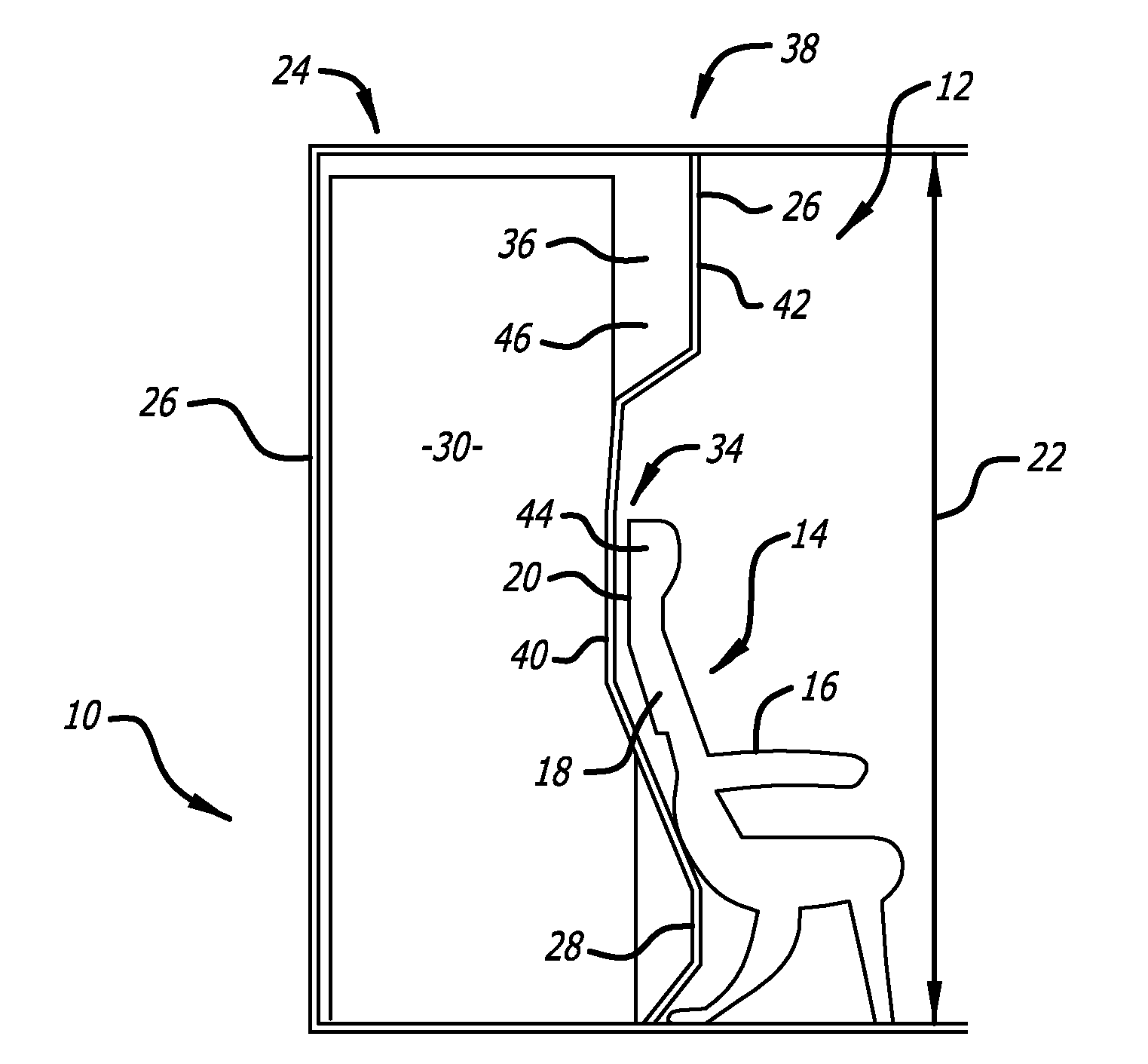
[0008]Briefly, and in general terms, the present invention provides for an enclosure, such as a lavatory, an aircraft closet, or an aircraft galley, for example, for a cabin of an aircraft including a structure having an aft portion with a substantially vertically extending exterior aft surface that is substantially not flat in a vertical plane. The enclosure structure permits a combination of the enclosure with the structure in a manner that permits significant saving of space in the aircraft, which in turn permits more seats to be installed, or more space to be offered per seat, increasing the value of the aircraft.

Problems solved by technology

The juxtaposition of these flat walled enclosures and contoured structures renders significant volumes unusable to both the function of the flat walled lavatory or enclosure and the function of the contoured seat or other structure.
Additionally, due to the lack of a provision for structural load sharing, conventional aircraft lavatories require a gap between the lavatory enclosures and adjacent structures, resulting in a further inefficiency in the use of space.
These provide a comfort advantage to passengers seated behind the bulkhead, but provide no increased efficiency in the use of space, in that they do not enable the seats fore and aft of the bulkhead to be placed more closely together.
These provide no improvement to the utility or spatial efficiency of the lavatory or other enclosure.
While they do provide some useful stowage for miscellaneous items, they do not provide sufficient additional stowage to provide more space for passenger seating.

Method used


Image

  • Aircraft interior lavatory
  • Aircraft interior lavatory

Examples


Embodiment Construction

[0019]Referring to the drawings, which are provided by way of example, and not by way of limitation, the present invention provides for an enclosure 10, such as a lavatory for a cabin 12 of an aircraft (not shown), although the enclosure may also be an aircraft closet, or an aircraft galley, or similar enclosed or structurally defined spaces, for example. As is illustrated in FIG. 2, the cabin includes a structure 14, and the enclosure may be taller than the cabin structure. The cabin structure can be a passenger seat 16, for example, installed immediately forward of the enclosure and having an aft portion 18 with and exterior aft surface 20 that is substantially not flat in a vertical plane 22. The lavatory includes a lavatory stall unit 24 having one or more walls 26 having a forward wall portion 28. The one or more walls define an interior lavatory space 30, and the forward wall portion is configured to be disposed immediately aft of and adjacent to or abutting the exterior aft s...


PUM


Abstract

A lavatory for an aircraft cabin includes a wall having a forward wall portion disposed immediately aft of and substantially conforming to an exterior aft surface of an aircraft cabin structure, such as a passenger seat, that is substantially not flat in a vertical plane. The forward wall portion includes a forward projection over an aft portion of the adjacent passenger seat. The forward wall portion can define a secondary space in the interior lavatory space, which can provide an amenity stowage space, and can include design elements providing visual space.

Description

CROSS-REFERENCES TO RELATED APPLICATIONS[0001]This application is based upon and claims priority from Provisional Application No. 61 / 326,198, filed Apr. 20, 2010, and Provisional Application No. 61 / 346,835, filed May 20, 2010, which are incorporated by reference in their entirety herein.BACKGROUND OF THE INVENTION[0002]The present invention relates generally to aircraft enclosures, and more particularly relates to an aircraft cabin enclosure, such as a lavatory, an aircraft closet, or an aircraft galley, for example, including an aircraft cabin structure having an aft portion with a substantially vertically extending exterior aft surface that is substantially not flat in a vertical plane.[0003]Aircraft lavatories, closets and other full height enclosures commonly have forward walls that are flat in a vertical plane. Structures such as passenger seats installed forward of such aircraft lavatories, closets and similar full height enclosures often have shapes that are contoured in the ...

Claims


Application Information

Patent Timeline
IPC IPC(8): B64D11/02B64D11/00
CPCB64D11/02B64C1/10Y02T50/46Y02T50/40B64D11/06B64F5/00B64D11/064
Inventor COOK, DONHARRINGTON, LIBERTYSTEINER, PHILIPPBRAUER, ROBERT K.
Owner BE AEROSPACE INCORPORATED
Why Eureka
Eureka Blog
Learn More