Eureka AIR delivers breakthrough ideas for toughest innovation challenges, trusted by R&D personnel around the world.

Device for operating a gripping or movement tool starting from an electric actuator

Active Publication Date: 2011-10-13
GIMATIC SRL
View PDF10 Cites 2 Cited by
  • Summary
  • Abstract
  • Description
  • Claims
  • Application Information

AI Technical Summary

Benefits of technology

[0008]An objective of the present invention is to improve the conditions and the precision of impulse of a gripper tool or electric control movement devices of the type mentioned above and to effectively resolve the above complained about problems regarding the known technique, simplifying furthermore the kinematic transmission of the motion by the electric actuator to the moveable member or members between two extreme positions and ensuring, where required, an item and objects gripping with an appropriate force also when they have different nominal dimensions.
[0015]of eliminating the necessity of having to resort to a sophisticated electronic and mechanical management of the electric actuator;

Problems solved by technology

The drawback that derives from it is not to be able to adapt to at least the active stroke and the gripper force in relation to the difference in the nominal dimensions of the items or objects that the tool is designed to grip.
The result is that in a case an item or object does not get correctly gripped and in the other case induces unwanted solicitations in the actuator and in the kinematic transmission of the motion.
In other words, the strokes of the gripper jaws depend directly on the rotation of the motor and if this is not chosen, adjusted and controlled with precision, the correct gripping action of the to of becomes incorrect.
Similar problems can be verified also in slide movement systems with a single member movable between two extreme positions defined by the stop.

Method used


Image

  • Device for operating a gripping or movement tool starting from an electric actuator
  • Device for operating a gripping or movement tool starting from an electric actuator
  • Device for operating a gripping or movement tool starting from an electric actuator

Examples


Embodiment Construction

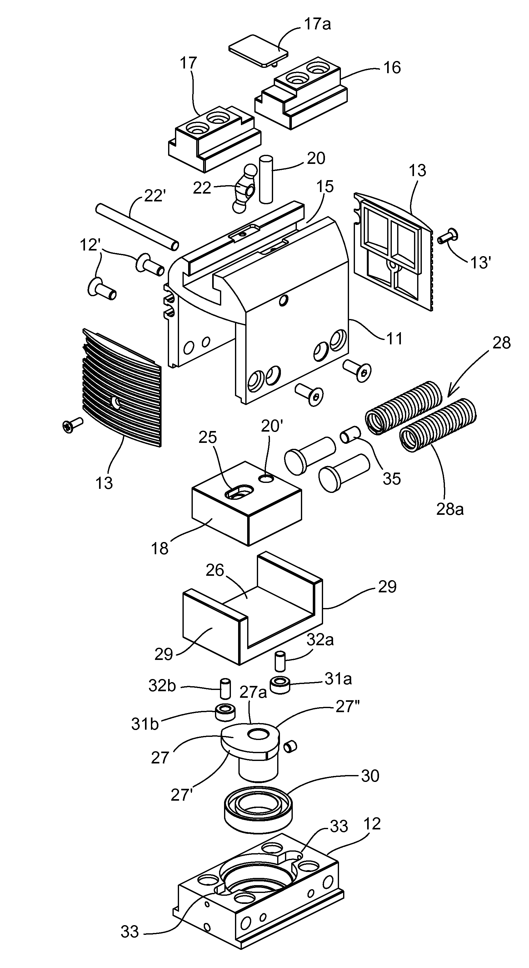
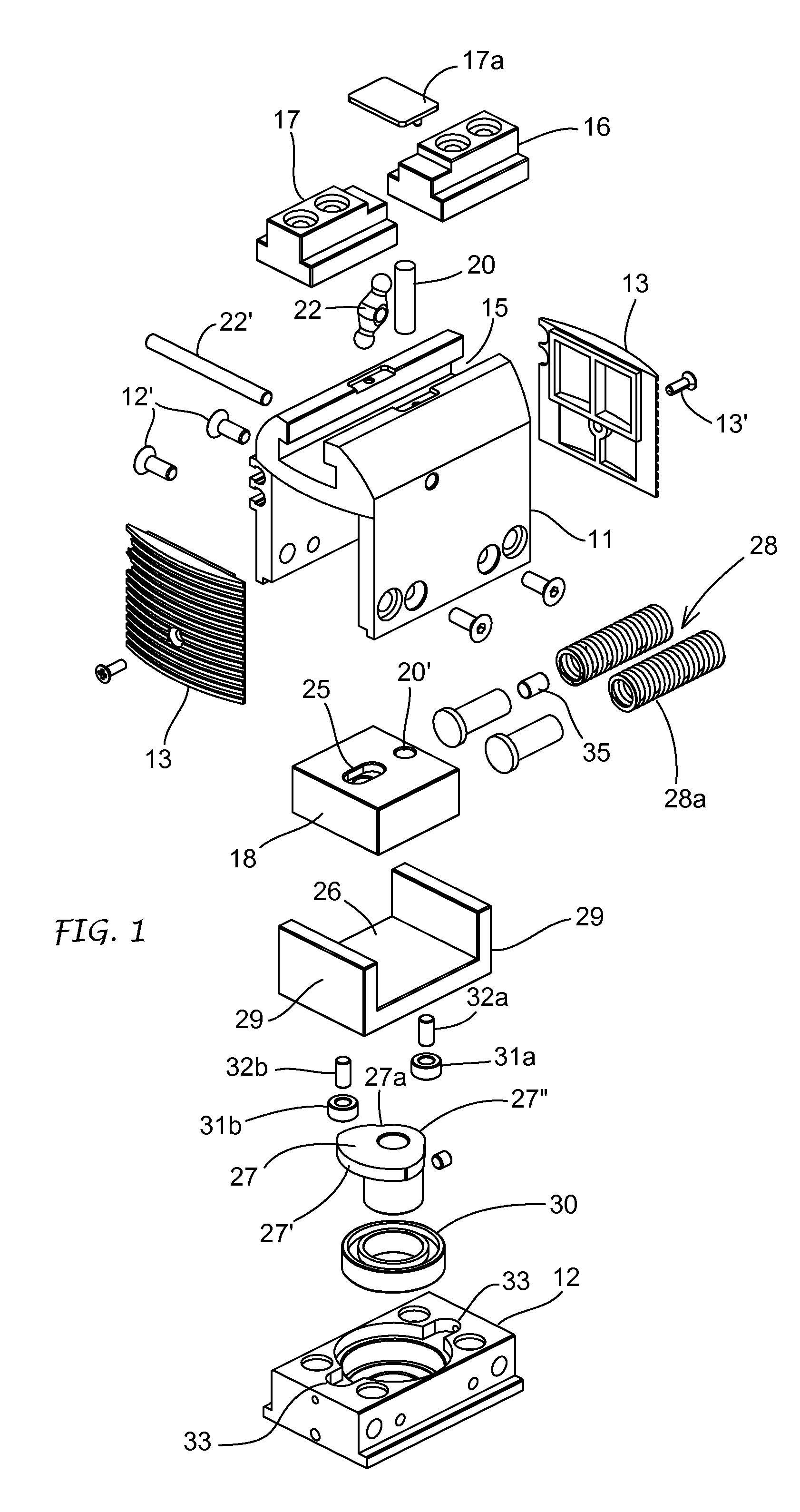
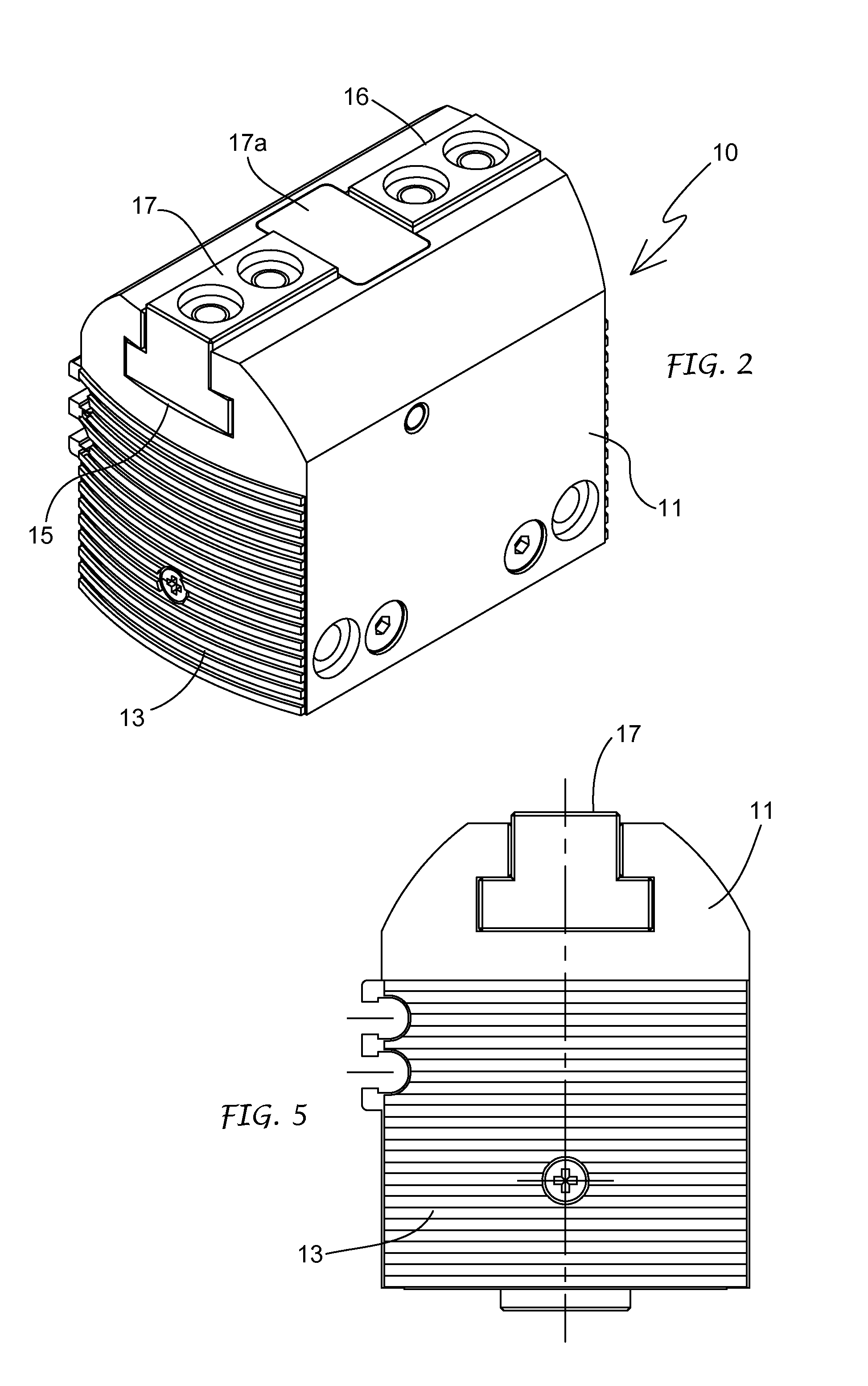
[0028]In the drawings is indicatively represented a gripper that basically comprises a gripper body 10 made up of a profile element 11 basically in an upside-down form U, to which a base plate 12 and two heads 13 at its opposite ends are fixed by screws 12′ respectively 13′ so as to delimit a chamber 14. On one of its sides, the one opposite the base plate 12, the body of the gripper 10 is provided with a guide groove 15 in which two mobile members in the shape of gripping jaws 16, 17 are guided and susceptible to movements in opposite directions, alternatively between a position in which they are approached and a position in which they are spread apart one from the other.

[0029]In particular, the guide groove 15 can have a an upside-down shape T, and the gripping jaws 16, 17 will be configured correspondingly to slide in said guide and result with the it top side facing the longitudinal opening of said guide groove 15.

[0030]The gripping jaws 16, 17 can be fixed from time to time to ...


PUM


Abstract

The invention concerns a device for operating gripping or movement tools provided at least with a movable member (16, 17) movable alternatively between a first and a second position distanced between them by a cursor (18) susceptible to controlled alter native linear movements starting from an electric actuator. The device comprises a transmission means (27) of the movement connected to the actuator, one towing slide (26) associated with the cursor (18) and susceptible to alternative movements caused by said actuator by means of said transmission means, and at least an elastic member (28) positioned preloaded between said towing slide (26) and said cursor (18) parallel both to their movement direction and to the movement direction of at least a mobile member. The cursor and the towing slide can both move rigidly together as long as the preload of the elastic means remains unchanged, both independently one with the other in reply to the variation of the preload of the elastic means deriving from a resistance against the movement of at least said mobile member.

Description

FIELD OF THE INVENTION[0001]The present invention relates to a device for operating gripping or movement tools, such as a gripper, a slide and the like, by means of an actuator, such as an electric control motor.STATE OF THE TECHNIQUE[0002]In the tools field for gripping items, objects or various bodies during their production and / or manipulation and / or assembly steps, well known are the grippers with two functional members in the form of gripping means provided with jaws and movable in opposite directions between two extreme positions, respectively active and inactive, that is to say closed and open. Movement systems are also well known as they have a member, for example of the slide type, provided with alternative forward and backward movements.[0003]In particular, said tools or gripper or movement systems can be of the pneumatic control or of the electric control type. In the case of pneumatic control grippers, the jaws are properly connected to and operated alternatively by a pi...

Claims


Application Information

Patent Timeline
IPC IPC(8): F16H25/14
CPCB25J15/0253Y10T74/18296
Inventor MAFFEIS, GIUSEPPE
Owner GIMATIC SRL
Why Eureka
Eureka Blog
Learn More