
Image forming apparatus with top-mounted photosensitive drum

Active Publication Date: 2011-10-06
AVISION
View PDF2 Cites 2 Cited by
  • Summary
  • Abstract
  • Description
  • Claims
  • Application Information

AI Technical Summary

Benefits of technology

[0008]Accordingly, the present invention has been proposed to solve the problems of the prior art, and it is an object of the present invention to provide an image forming apparatus with a top-mounted photosensitive drum and a resilient member, for example, a compression spring, for counteracting the weight of a developing cartridge, in order to maintain steady contact pressure between the developing roller and the photosensitive drum and to reduce the wear of the photosensitive drum.
[0009]To achieve the above-identified object, the present invention provides an image forming apparatus including a case, a photosensitive drum, a developing cartridge and a resilient member. The photosensitive drum, disposed over the developing cartridge, forms a toner image. The developing cartridge is movably disposed within the case and includes a developing tank and a developing roller. The developing roller is mounted on the developing tank and positioned opposite the photosensitive drum. The developing roller transfers toners to the photosensitive drum. The resilient member, disposed between the developing tank and the case, provides a restoring force for counteracting a weight of the developing tank and urging the developing roller towards the photosensitive drum.
[0010]The image forming apparatus of the present invention maintains a steady and tight contact between the top-mounted photosensitive drum and the developing roller without applying excessive pressure on the photosensitive drum. Therefore, no abnormal tear and wear will be produced on the photosensitive drum, and endurability of the photosensitive drum is remarkably improved.

Problems solved by technology

Therefore, the pressing contact between the photosensitive drum and the developing roller of the developing unit produces excessive friction therebetween.
Consequently, the increase in friction causes rapid wear of the photosensitive film of the photosensitive drum and shortens the life of the photosensitive drum.
However such high level of pressure on the photosensitive drum only accelerates a deterioration of the photosensitive drum and consequent impact on images is liable to occur.
In addition, in the situation where the developing unit is mounted in a case with a lock device pushing the developing unit towards the photosensitive drum, the increase in the pressure applied on the photosensitive drum causes the expedited deterioration as well .

Method used


Image

  • Image forming apparatus with top-mounted photosensitive drum
  • Image forming apparatus with top-mounted photosensitive drum
  • Image forming apparatus with top-mounted photosensitive drum

Examples


Embodiment Construction

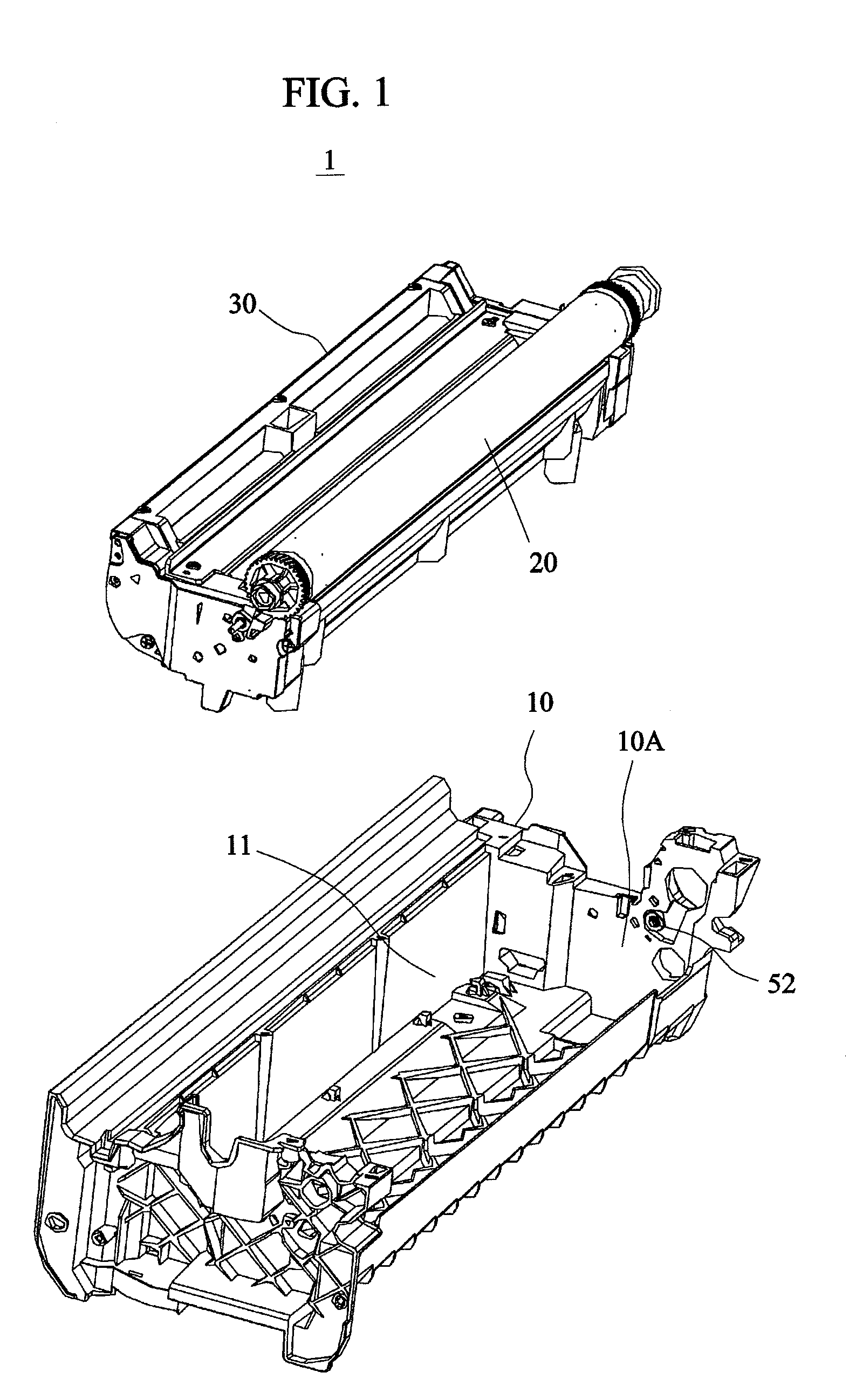
[0018]FIG. 1 is an exploded pictorial view of an image forming apparatus 1 according to a first embodiment of the present invention. Referring to FIG. 1, the image forming apparatus 1 includes a case 10, a photosensitive drum 20 and a developing cartridge 30. The photosensitive drum 20, disposed over the developing cartridge 30, forms a toner image. The developing cartridge 30 is accommodated within a chamber 11 of the case 10. A roller 52 is rotatable and mounted on a sidewall of the chamber 11.

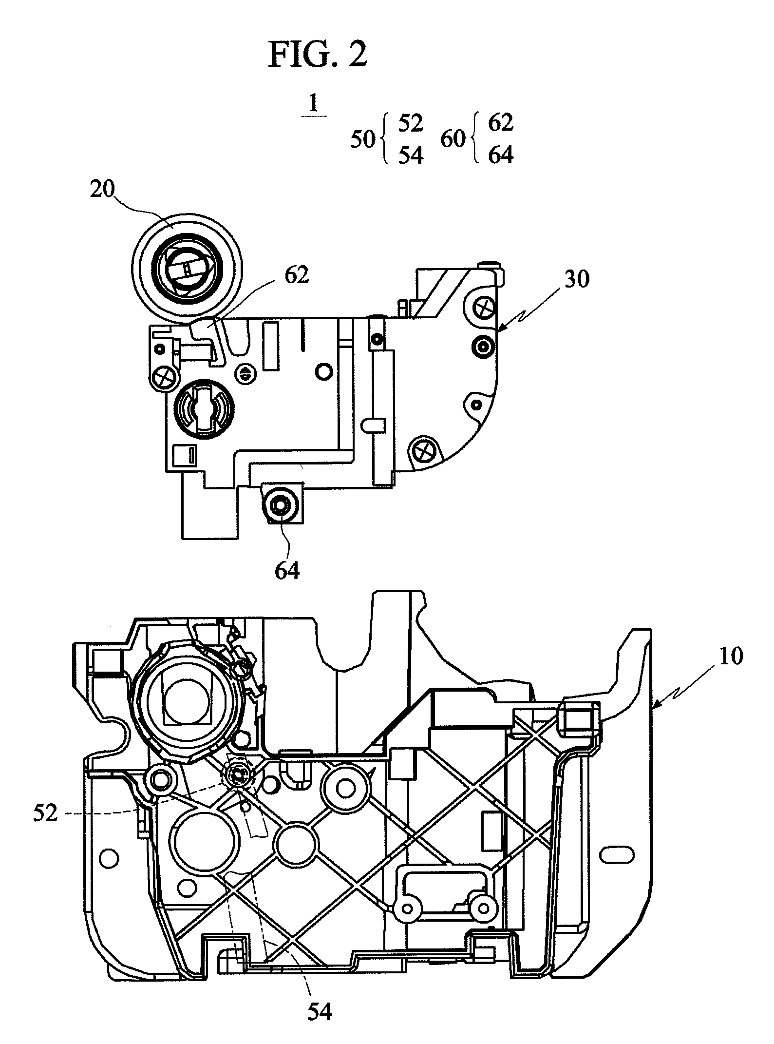
[0019]FIG. 2 is an exploded side view of the image forming apparatus 1 according to the first embodiment of the present invention. As shown in FIG. 2, the roller 52 is depicted in dashed lines. FIG. 3 is a simplified drawing of FIG. 2. In FIG. 3, the case 10 is shown in a simplified form, omitting parts of its structure non-essential in this present invention, in order to improvevisibility of a supporting member set 50 (to be described later) depicted in phantom lines of FIG. 2. In addition,...


PUM


Abstract

An image forming apparatus includes a case, a photosensitive drum, a developing cartridge and a resilient member. The photosensitive drum forms a toner image. The developing cartridge, movably disposed within the case, includes a developing tank and a developing roller. The developing roller, mounted on the developing tank and positioned opposite the photosensitive drum, transfers toners to the photosensitive drum. The resilient member, disposed between the developing tank and the case, provides a restoring force for counteracting a weight of the developing tank and urging the developing roller towards the photosensitive drum.

Description

[0001]This application claims priority of No. 099109793 filed in Taiwan R.O.C. on Mar. 31, 2010 under 35 USC 119, the entire content of which is hereby incorporated by reference.BACKGROUND OF THE INVENTION[0002]1. Field of the Invention[0003]The present invention relates in general to an image forming apparatus, and more particularly to an image forming apparatus with a top-mounted photosensitive drum and being capable of reducing wear of the photosensitive drum.[0004]2. Related Art[0005]In a conventional printer, the photosensitive drum, which is mounted at the side of or under the developing unit, constantly withstands a weight or a lateral locking force of the developing unit, especially when the developing unit contains a toner supplier. Therefore, the pressing contact between the photosensitive drum and the developing roller of the developing unit produces excessive friction therebetween. Consequently, the increase in friction causes rapid wear of the photosensitive film of the...

Claims


Application Information

Patent Timeline
IPC IPC(8): G03G15/08
CPCG03G15/0813
Inventor CHUEH, CHUANG-HUAGOTODA, KATSUHIKO
Owner AVISION
Learn More