
Hand-Wearing Assembly

a technology for handwearing and assembly, which is applied in the direction of cycle equipment, lighting support devices, instruments, etc., can solve the problems of difficult to be adjusted to a precise position, the position of the illuminating device cannot be adjusted, and the position of the side mirror cannot be adjusted. , to achieve the effect of convenient adjustmen

Active Publication Date: 2011-09-29
CHEN YI YI
View PDF6 Cites 11 Cited by
  • Summary
  • Abstract
  • Description
  • Claims
  • Application Information

AI Technical Summary

Benefits of technology

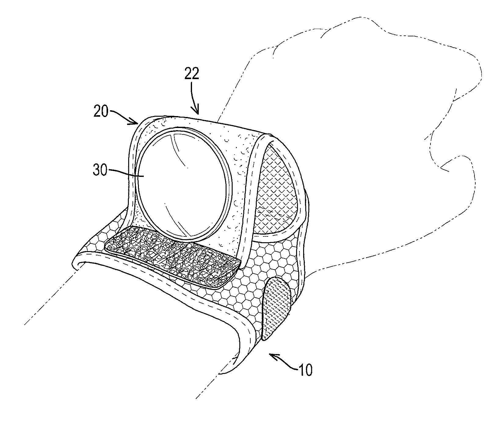
[0011]A hand-wearing assembly has a main body and a side mirror mount. The main body is a loop and has a connecting top. The side mirror mount is connected with and stands on the connecting top and has a mirror face facing a rear end of the connecting top and is capable of being connected with a side mirror. The side mirror mount allows the side mirror to stand above a wrist or a back of a hand. Accordingly, a rider can see a rear sight at ease via the standing mirror. With a slight movement of the hand, the position of the side mirror is easily adjusted to enable the rider to see all the rear area from all directions, or to check the positions of the following cyclists.

Problems solved by technology

Because the side mirror is mounted securely on the bicycle or the motorcycle, the position of the side mirror cannot be adjusted, or is difficult to be adjusted to a precise position for the rider to see the backward condition, such as a following cyclist.
The position of the illuminative device cannot be adjusted, or is difficult to be adjusted toward a desired illuminative direction.

Method used


Image

  • Hand-Wearing Assembly
  • Hand-Wearing Assembly
  • Hand-Wearing Assembly

Examples


Embodiment Construction

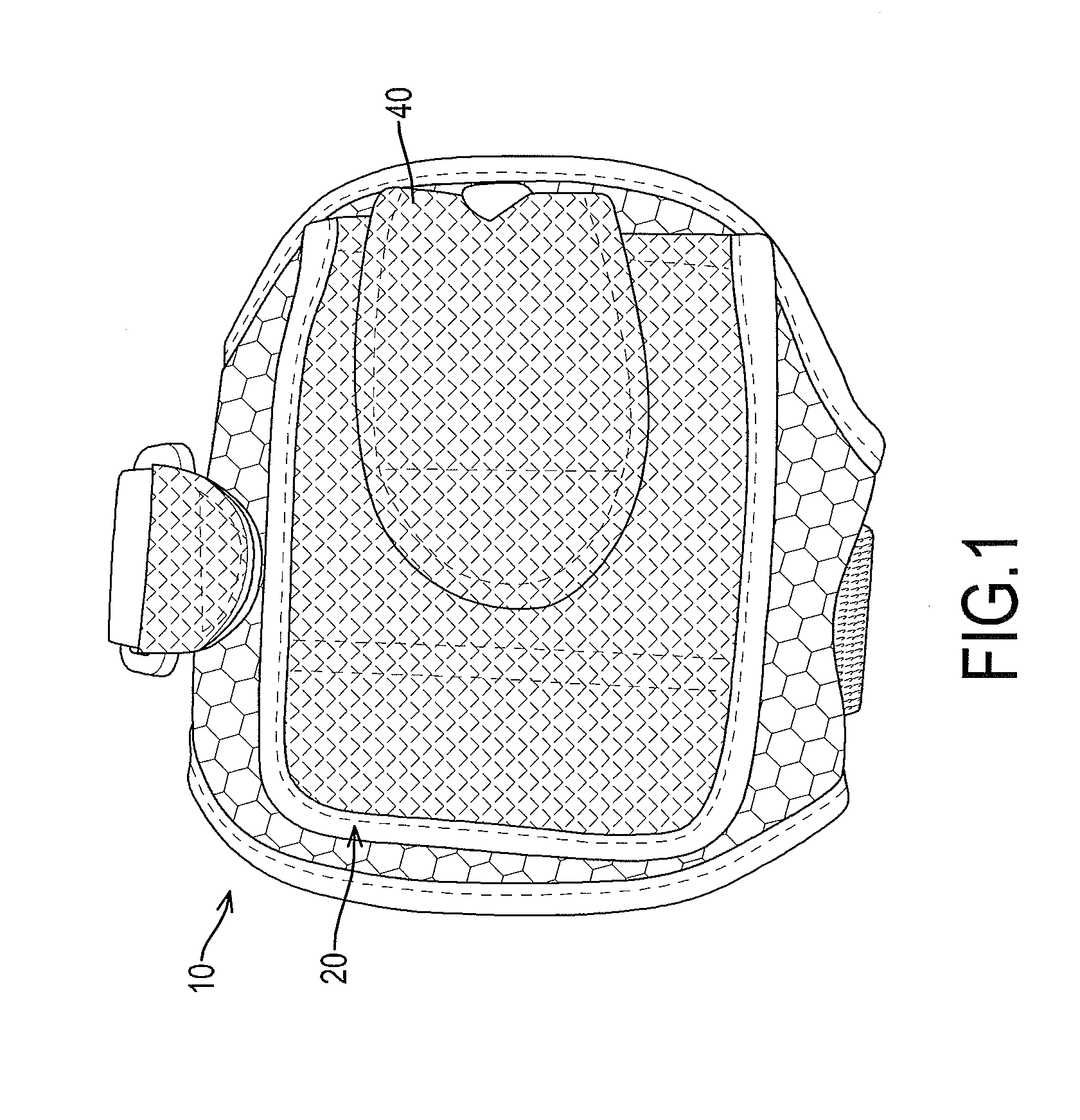
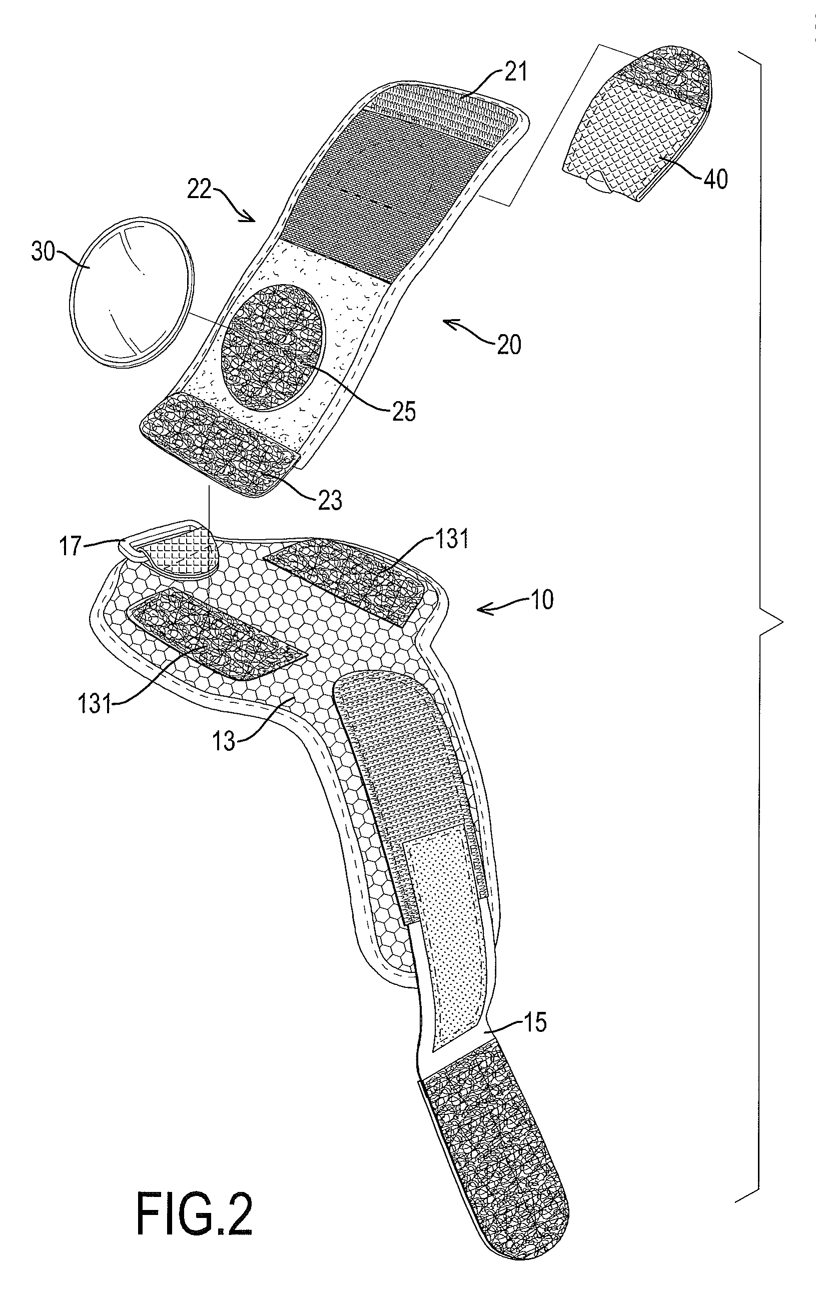
[0021]With reference to FIGS. 1 to 3, a first embodiment of a hand-wearing assembly in accordance with the present invention comprises a main body 10, a side mirror mount 20, a side mirror 30 and an LED (light emitting diode) assembly 40.

[0022]The main body 10 is a loop and has a wearing hole and a connecting top 13. The wearing hole is formed through the main body 10 to allow a rider to wear the hand-wearing assembly on a wrist or a back of a hand. The connecting top 13 is located above the wearing hole and has a front end and a rear end opposite to the front end of the connecting top 13.

[0023]Preferably, the connecting top 13 has two connecting areas 131 respectively formed at the front end and the rear end of the connecting top 13. Preferably, the main body 10 is a wristlet having a ring 17 and a belt 15. The belt 15 is mounted through the ring 17.

[0024]With reference to FIGS. 2 to 4, the side mirror mount 20 is connected with and stands on the connecting top 13. Preferably, the ...


PUM


Abstract

A hand-wearing assembly has a main body and a side mirror mount. The main body is a loop and has a connecting top. The side mirror mount is connected with and stands on the connecting top and has a mirror face facing a rear end of the connecting top and is capable of being connected with a side mirror. The side mirror mount allows the side mirror to stand above a wrist or a back of a hand. Accordingly, a rider can see a rear sight at ease via the standing mirror. With a slight movement of the hand, the position of the side mirror is easily adjusted to enable the rider to see all the rear area from all directions, or to check the positions of the following cyclists.

Description

BACKGROUND OF THE INVENTION[0001]1. Field of the Invention[0002]The present invention relates to a hand-wearing assembly, and more particularly to a hand-wearing assembly on which a side mirror can stand.[0003]2. Description of Related Art[0004]Problems that a rider may encounter when riding a bicycle or a motorcycle are as follows:[0005]1. Difficult adjustment of a position of a side mirror:[0006]Because the side mirror is mounted securely on the bicycle or the motorcycle, the position of the side mirror cannot be adjusted, or is difficult to be adjusted to a precise position for the rider to see the backward condition, such as a following cyclist.[0007]2. Difficult adjustment of a position of an illuminative device:[0008]Like the side mirror, the illuminative device is mounted securely on the bicycle or the motorcycle. The position of the illuminative device cannot be adjusted, or is difficult to be adjusted toward a desired illuminative direction.[0009]To overcome the shortcoming...

Claims


Application Information

Patent Timeline
IPC IPC(8): G02B7/182F21V21/08
CPCG02B7/002B62J29/00
Inventor CHEN, YI-YI
Owner CHEN YI YI
Learn More