
System and method to define, visualize and manage a composite service group in a high-availability disaster recovery environment

a disaster recovery environment and composite service technology, applied in the field of digital computer systems, can solve the problems of serious damage to business operations, permanent data loss, and likely serious negative consequences for the continued viability of a business, and achieve the effect of convenient definition

Active Publication Date: 2011-09-15
VERITAS TECH
View PDF6 Cites 29 Cited by
  • Summary
  • Abstract
  • Description
  • Claims
  • Application Information

AI Technical Summary

Benefits of technology

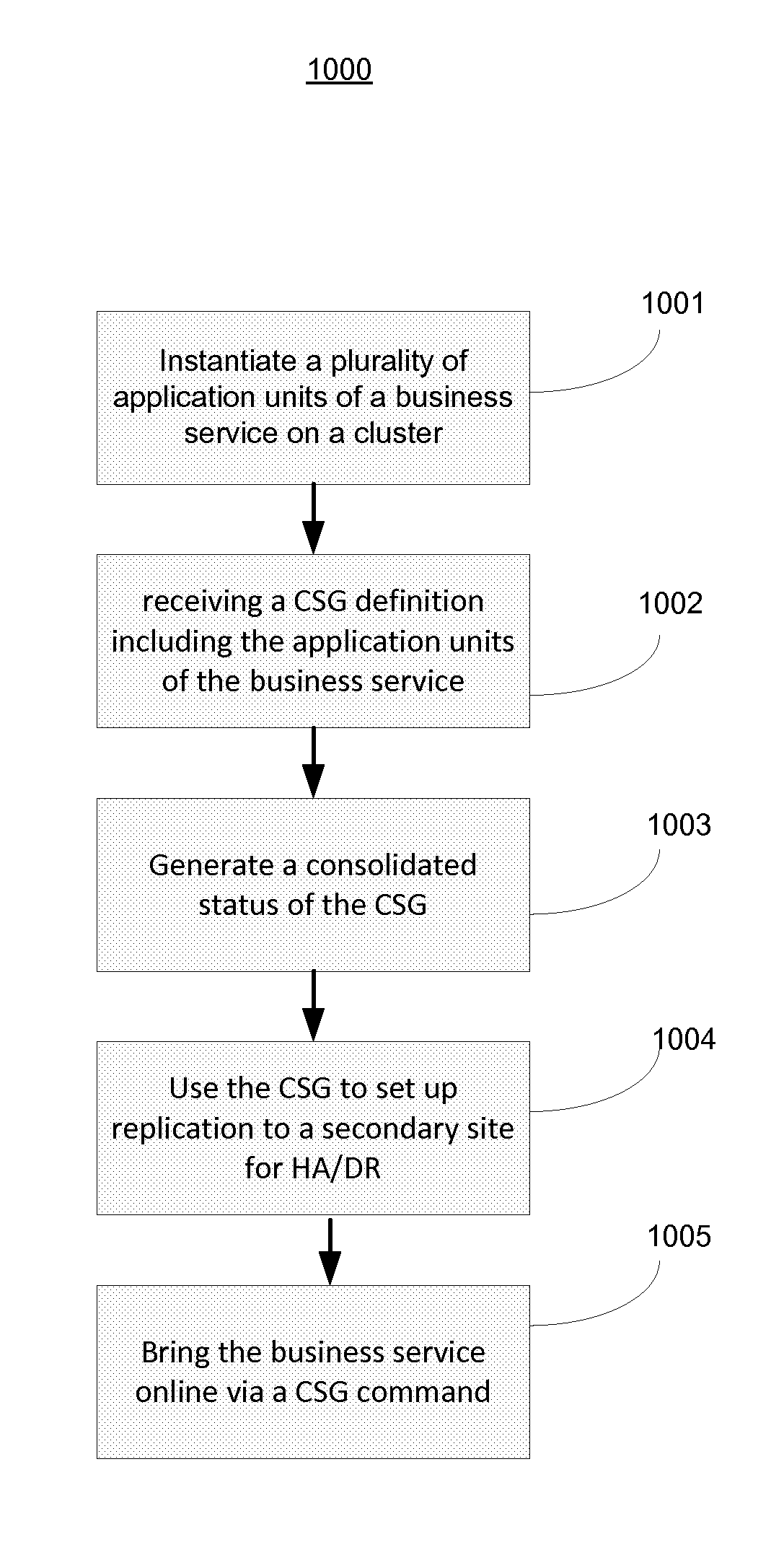
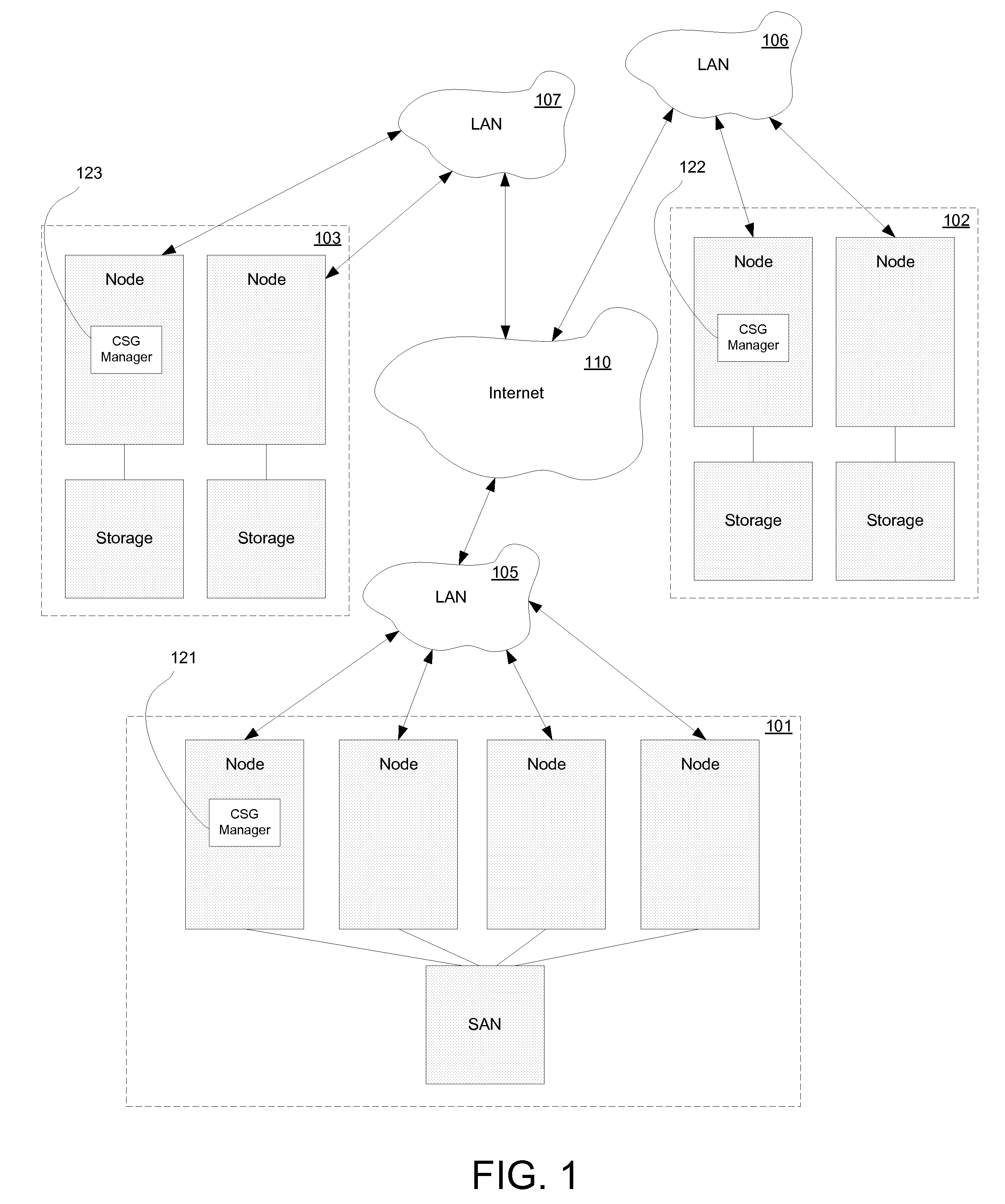
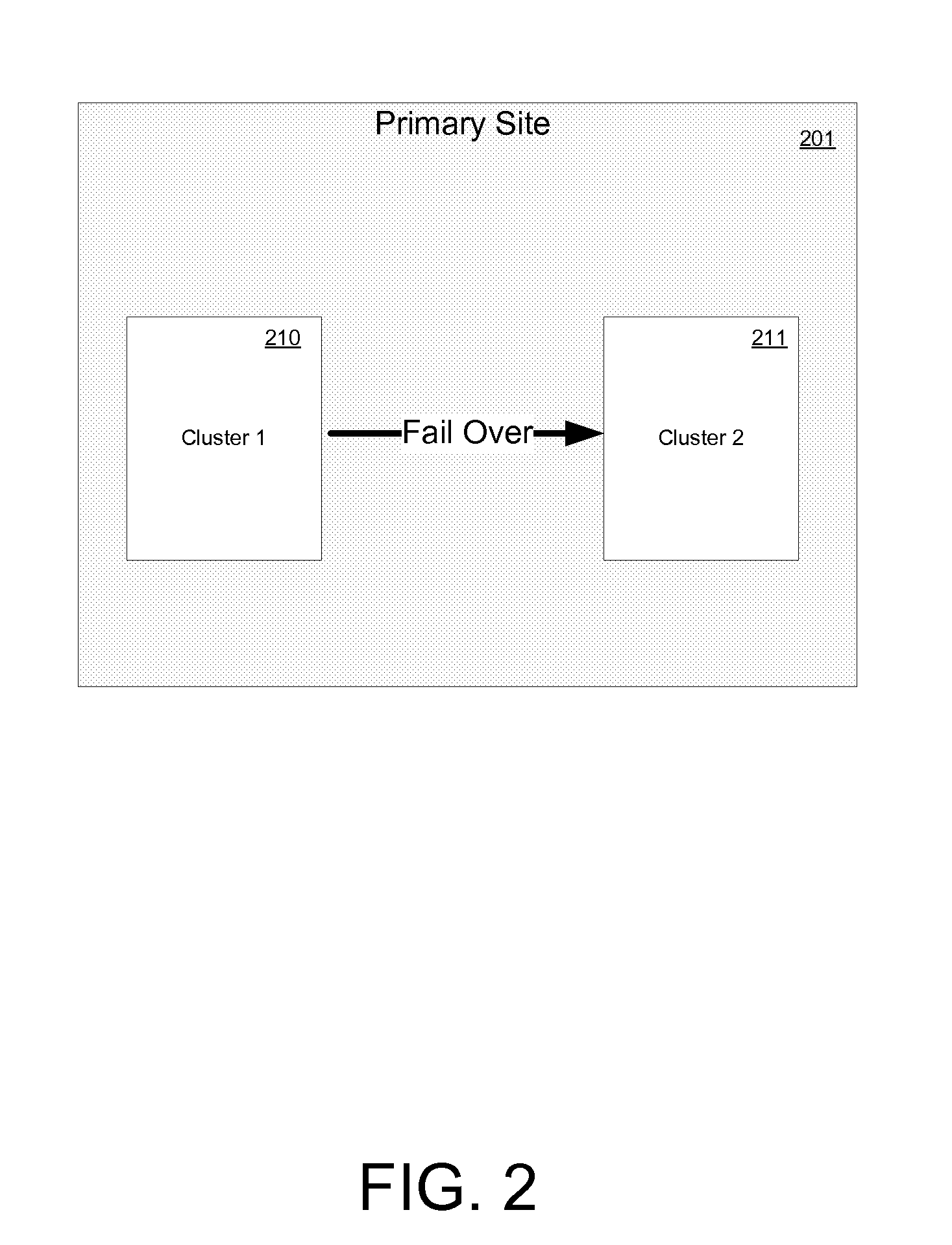
The present invention provides a method and computer system for easily defining, managing, and providing high-availability and disaster recovery for multi-tier business services within and across clusters. The invention includes a composite service group that encapsulates dependencies, constraints, and system placement strategies for application units that implement the business service. The composite service group can be used for failover between clusters and provides administrative control of the application units. It also allows for a replication process between a primary and secondary site for high availability or disaster recovery. Overall, the invention simplifies the process of managing complex business services and ensures their reliability and availability.

Problems solved by technology

Unplanned events that inhibit the availability of this data can seriously damage business operations.
Additionally, any permanent data loss, from natural disaster or any other source, will likely have serious negative consequences for the continued viability of a business.
Normally, if a server with a particular application crashes, the application will be unavailable until someone fixes the crashed server.
For example, a flood, hurricane, earthquake, or the like, can disrupt services and infrastructure across wide areas.

Method used


Image

  • System and method to define, visualize and manage a composite service group in a high-availability disaster recovery environment
  • System and method to define, visualize and manage a composite service group in a high-availability disaster recovery environment
  • System and method to define, visualize and manage a composite service group in a high-availability disaster recovery environment

Examples


Embodiment Construction

[0036]Although the present invention has been described in connection with one embodiment, the invention is not intended to be limited to the specific forms set forth herein. On the contrary, it is intended to cover such alternatives, modifications, and equivalents as can be reasonably included within the scope of the invention as defined by the appended claims.

[0037]In the following detailed description, numerous specific details such as specific method orders, structures, elements, and connections have been set forth. It is to be understood however that these and other specific details need not be utilized to practice embodiments of the present invention. In other circumstances, well-known structures, elements, or connections have been omitted, or have not been described in particular detail in order to avoid unnecessarily obscuring this description.

[0038]References within the specification to “one embodiment” or “an embodiment” are intended to indicate that a particular feature, ...


PUM


Abstract

A method for defining and managing a composite service group for a cluster based computer system is disclosed. The method includes instantiating a plurality of application units on a cluster based computer system, wherein the application units implement a business service. The method further includes receiving a composite service group definition, wherein a composite service group enumerates application units, out of the plurality of application units, that implement the business service, and generating a consolidated status of the composite service group. The business service is then started (online) / stopped (offline) / migrated / failed-over / failed-back in accordance with the consolidated status, as a single unit, by using the composite service group.

Description

FIELD OF THE INVENTION[0001]The present invention is generally related to digital computer systems, more particularly, to the management of multi-tier applications.BACKGROUND OF THE INVENTION[0002]Information drives business. Companies today rely to an unprecedented extent on online, frequently accessed, constantly changing data to run their businesses. Unplanned events that inhibit the availability of this data can seriously damage business operations. Additionally, any permanent data loss, from natural disaster or any other source, will likely have serious negative consequences for the continued viability of a business. Therefore, when disaster strikes, companies must be prepared to eliminate or minimize data loss, and recover quickly with useable data.[0003]Companies have come to rely upon high-availability clusters to provide the most critical services and to store their most critical data. In general, there are different types of clusters, such as, for example, compute clusters...

Claims


Application Information

Patent Timeline
Patent Type & Authority Applications(United States)
IPC IPC(8): G06Q10/00G06Q50/00
CPCG06Q10/101G06F11/2023
Inventor GAWALI, ASHISH LAXMANRAOMUKHERJEE, ARINDAMRANGARI, AMIT HARIDASSUNDARALINGAM, KALYANIKAIPA, SIRISHA SURYANARAYAN
Owner VERITAS TECH
Learn More