
Method and system for shot tracking

a shot tracking and method technology, applied in the field of shot tracking, can solve the problems of lack of a method and a system of measurement in the early ar

Active Publication Date: 2011-09-15
TOPGOLF CALLAWAY BRANDS CORP
View PDF66 Cites 44 Cited by
  • Summary
  • Abstract
  • Description
  • Claims
  • Application Information

AI Technical Summary

Benefits of technology

[0008]The present invention is novel in that the observation of the relative motion does not depend on near visible light and uses a coherent pattern to capture the position of the club relative the ground antenna transmitter/receiv

Problems solved by technology

The prior art is lacking in a method and system to measure the motion of the club through measurement of the shaft.

Method used


Image

  • Method and system for shot tracking
  • Method and system for shot tracking
  • Method and system for shot tracking

Examples


Embodiment Construction

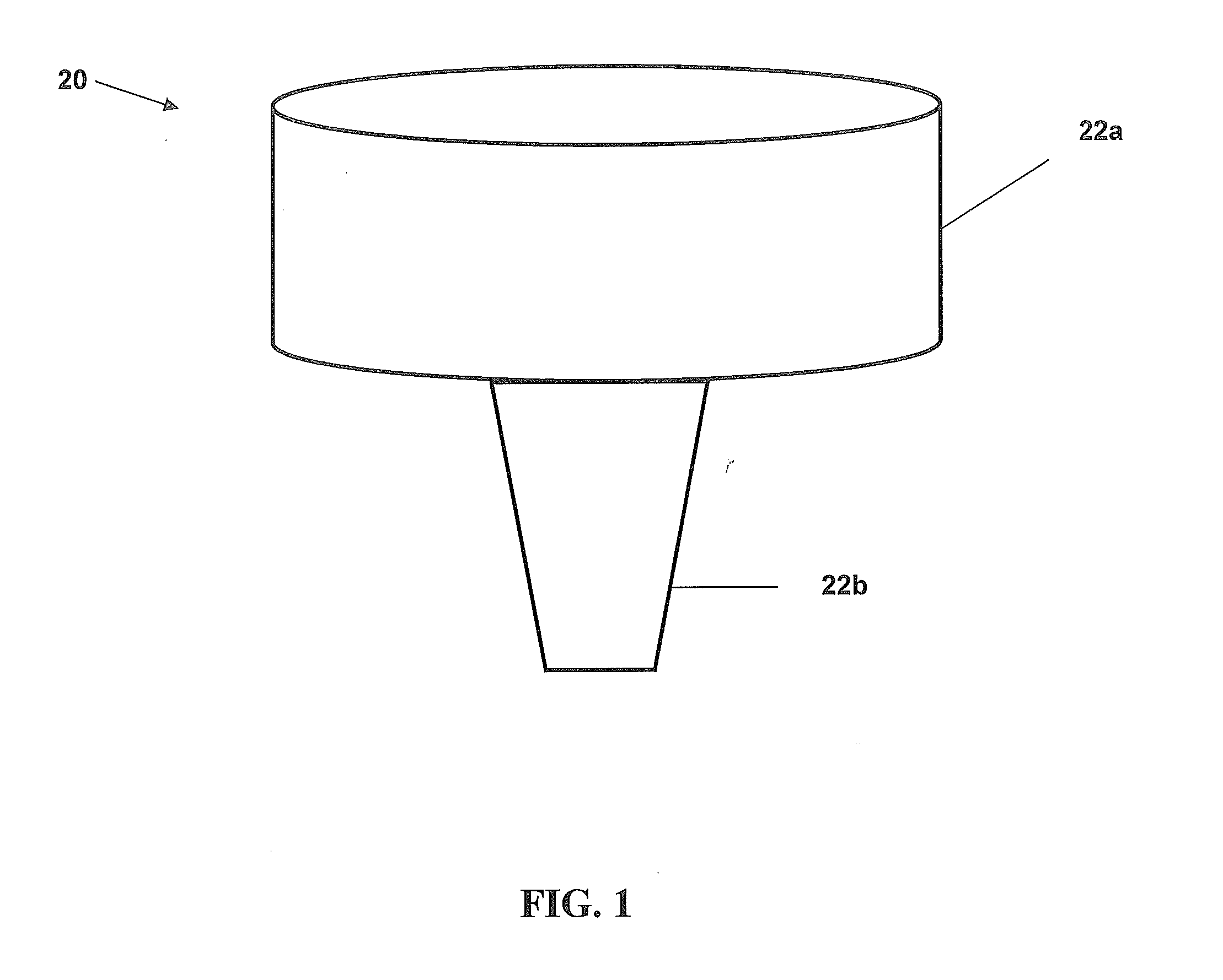
[0018]FIG. 1 is a perspective view of the device for shot tracking.

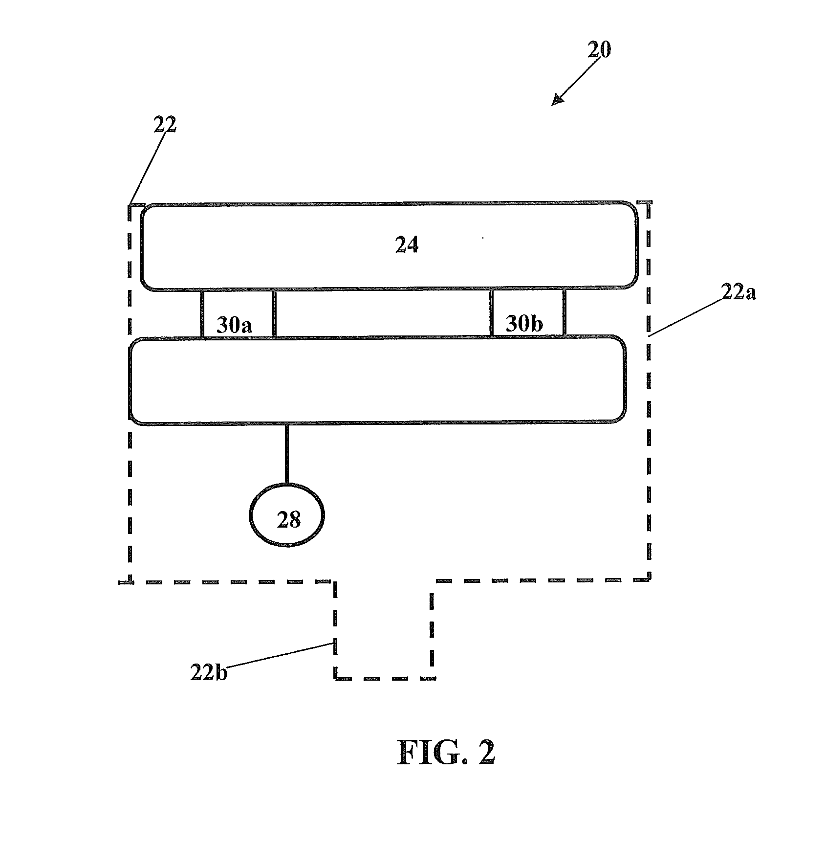
[0019]FIG. 2 is a perspective view of components of a device for shot tracking, including the main body and projection body extending downward.

[0020]FIG. 3 shows the housing component of the shot tracking device and illustrates the diameter.

[0021]FIG. 4 is an illustration of the circuit diagram of the components of a device for shot tracking.

[0022]FIG. 5 is a flow chart of a method of shot tracking.

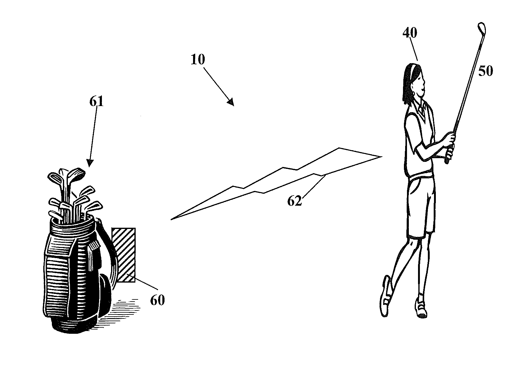
[0023]FIG. 6 illustrates the system 20. A transponder in a golf club 50 swung by a golfer sends a signal 62 to a receiver 60. The receiver is attached to a golf bag 61, however, those skilled within the pertinent art will recognize that the receiver may be attached to any pertinent device including the golfer, or may stand alone.

[0024]This invention is a method 1000 for predicting a golfer's swing speed. The method 1000 comprises determining that a golfer is addressing a golf ball to swing a golf club 50, wherein the golf ...


PUM


Abstract

A method for predicting a golfer's swing speed, wherein the method comprises determining that the golfer is addressing a golf ball to swing a golf club, monitoring a backswing, determining a transition time, monitoring a downswing, determining an impact time, transmitting data for the golfer's swing to a receiver for analysis and generating a golfer's swing speed using a length of a shaft of the golf club.

Description

CROSS REFERENCES TO RELATED APPLICATIONS[0001]The present application is a continuation in part of U.S. patent application Ser. No. 12 / 720,369 filed on Mar. 9, 2010, U.S. patent application Ser. No. 12 / 779,653 filed on May 13, 2010 and U.S. patent application Ser. No. 12 / 838,656 filed on Jul. 19, 2010.STATEMENT REGARDING FEDERALLY SPONSORED RESEARCH OR DEVELOPMENT[0002]Not ApplicableBACKGROUND OF THE INVENTION[0003]1. Field of the Invention[0004]The present invention relates to shot tracking. More specifically, the present invention relates to a method and system for tracking shots of a golfer during a round of golf.[0005]2. Description of the Related Art[0006]Golf clubs combine with the players swing to propel a ball toward a favored location and through a favored path. The orientation and speed of the club head at impact largely determines the ball path including carry distance and roll.[0007]The prior art is lacking in a method and system to measure the motion of the club through...

Claims


Application Information

Patent Timeline
IPC IPC(8): A63B69/36
CPCA63B24/0021G01S19/19A63B69/3658A63B2024/0028A63B2024/0031A63B2024/0037A63B2071/063A63B2071/0691A63B2220/12A63B2220/14A63B2220/20A63B2220/40A63B2220/807A63B2225/50A63B2225/54A63B2243/0029A63B57/00A63B2102/32A63B60/46
Inventor DENTON, SCOTTBALARDETA, JOSEPH
Owner TOPGOLF CALLAWAY BRANDS CORP
Learn More