
Washing Machine

Active Publication Date: 2011-08-18
LG ELECTRONICS INC
View PDF11 Cites 3 Cited by
  • Summary
  • Abstract
  • Description
  • Claims
  • Application Information

AI Technical Summary

Benefits of technology

Therefore, an object of the present invention is to provide a washing machine in which the space within

Problems solved by technology

Thus, the presence of the driving motors between the rear wall of the tub 3 and the rear surface of the main body hampers the use of the internal space of the main body 5 of the washing machine, resulting in the limitation in the floor area ratio of the tub 5 or the drum 9, name

Method used


Image

  • Washing Machine
  • Washing Machine
  • Washing Machine

Examples


Example

Reference will now be made in detail to the preferred embodiments of the present invention, examples of which are illustrated in the accompanying drawings.

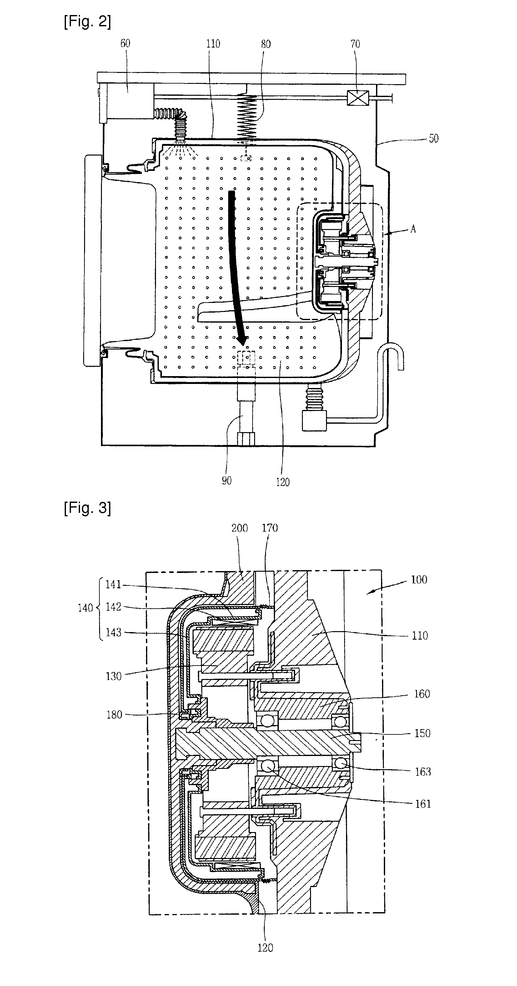
FIG. 2 is a vertical sectional view of a washing machine according to an exemplary embodiment of the present invention.

As shown in FIG. 2, the washing machine according to an exemplary embodiment of the present invention includes: a main body 50 forming an eternal appearance; a tub 110 installed at the interior of the main body 50 and keeping washing water in storage, a drum 120 rotatably installed within the tub 110 and receiving the laundry inputted thereto, driving motors 130 and 140 configured to rotate the drum 120, a rotational shaft 150 configured to transfer a rotational force of the driving motors 130 and 140 to the drum 120, bearings 161 and 163 supporting the rotational shaft 150, a detergent supply device 60 configured to supply water mixed with a detergent to the tub 110, and a water supply device 70 including a plura...


PUM


Abstract

A washing machine includes: a main body forming an external appearance; a tub installed at an inner side of the main body and keeping washing water in storage; a drum rotatably installed at the inner side of the tub; a rotational shaft coupled with the drum to transfer a driving force; a driving motor installed between the tub and the drum to rotate the rotational shaft; and a gasket installed between the drum and the tub and preventing leaked washing water from being introduced to the driving motor.

Description

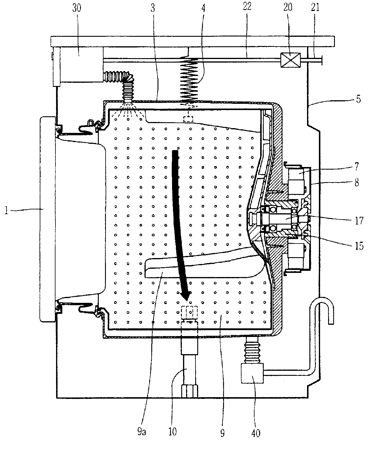
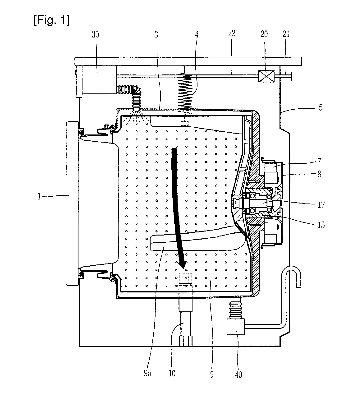
TECHNICAL FIELDThe present invention relates to a washing machine and, more particularly, to a washing machine in which a driving motor for rotating a drum is disposed at an inner side of a washing machine tub.BACKGROUND ARTIn general, a washing machine is a device in which in a state that washing water is supplied to the interior of a drum in which the laundry has been input to be placed, the drum is rotated in a forward direction or in a backward direction to allow the laundry within the drum to collide with the washing water so as to wash dirt or stain off the laundry by using energy generated according to the collision between the laundry and the washing water.FIG. 1 illustrates the configuration of a general washing machine. As shown in FIG. 1, the general washing machine includes a main body 5, a tub 3 installed at the interior of the main body 5 and keeping washing water in storage, a drum 9 rotatably installed within the tub 3 and receiving the laundry inputted thereto, driv...

Claims


Application Information

Patent Timeline
IPC IPC(8): D06F21/00
CPCD06F37/04D06F37/30D06F37/206D06F37/304D06F37/266D06F37/22
Inventor JUN, CHA-SEUNGMIN, BYOUNG-WOOKLEE, DONG-CHEOL
Owner LG ELECTRONICS INC
Learn More