Cutting mechanism for dry film laminator

Active Publication Date: 2011-08-04
C SUN MFG
View PDF4 Cites 4 Cited by
  • Summary
  • Abstract
  • Description
  • Claims
  • Application Information

AI Technical Summary

Benefits of technology

[0007]The main objective of the present invention is to provide an improved cutting mechanism for dry film laminator.

Problems solved by technology

However, during trimming, the bleeding resin would not be removed clearly.
The resin may bleed out the wafer again.
Therefore, the wafer fabrication may have a low yield.

Method used


Image

  • Cutting mechanism for dry film laminator
  • Cutting mechanism for dry film laminator
  • Cutting mechanism for dry film laminator

Examples


Embodiment Construction

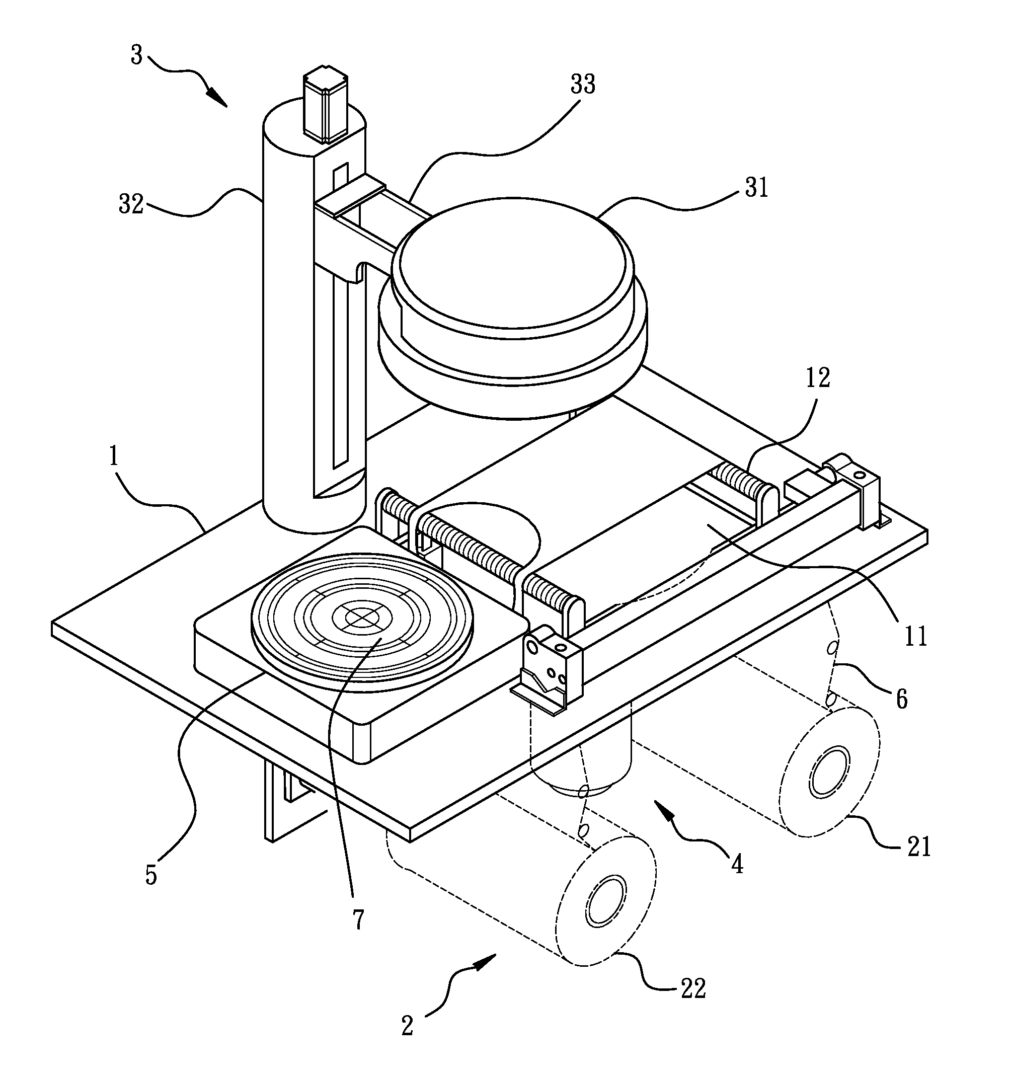
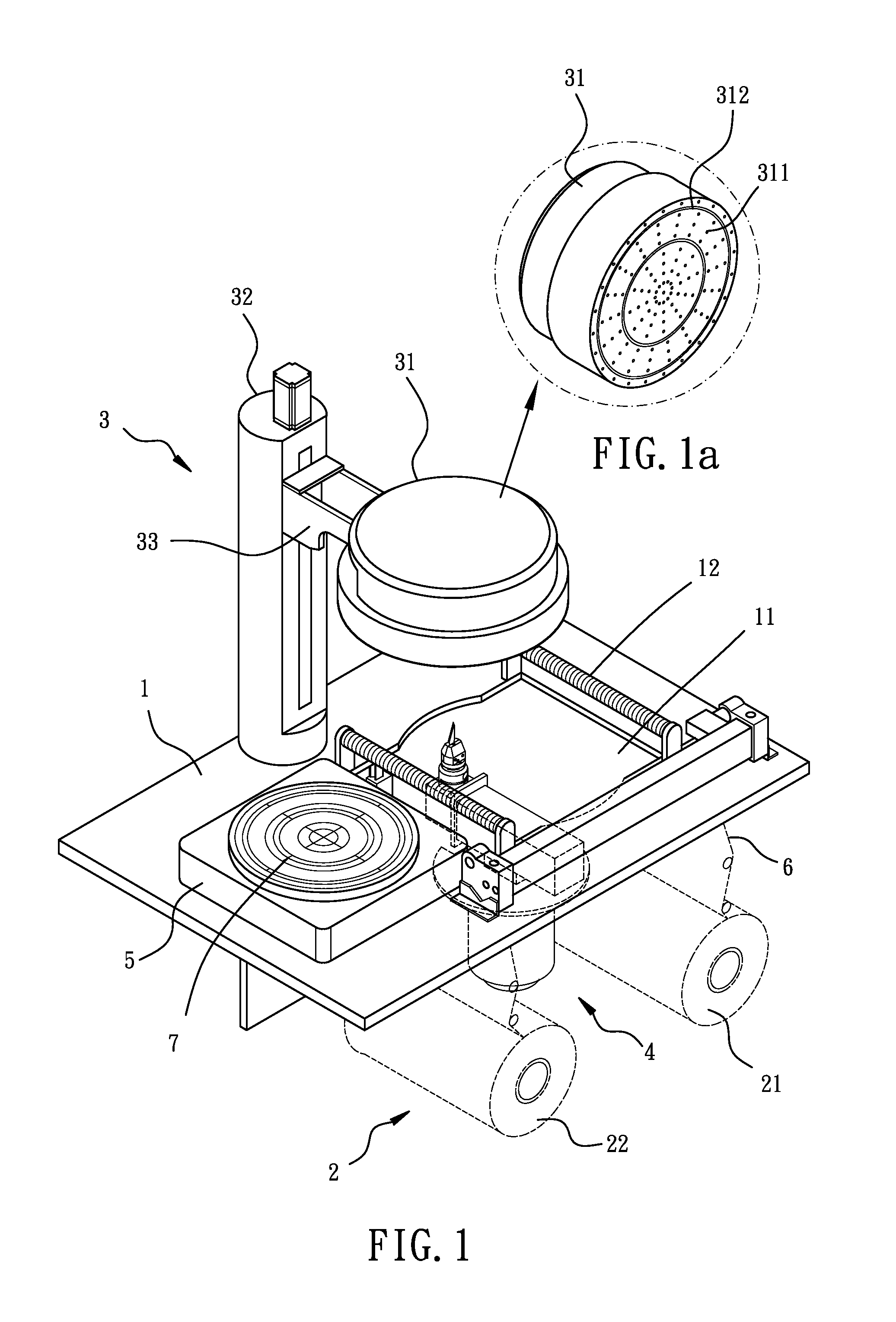
[0021]Referring to the drawings and initially to FIGS. 1-2, a cutting mechanism for dry film laminator in accordance with the present invention comprises a main base 1 adapted to be connected to a dry film laminator (not shown). The main base 1 has a cutting space 11 defined therein and extending therethrough. A support base 5 is disposed on a top of the main base 1 and located adjacent to the cutting space 11 for adapting to hold a wafer 7. The main base 1 has two rollers 12 disposed on the top thereof and oppositely located beside the cutting space 11.

[0022]A film supply device 2 is disposed on a bottom of the main base 1. The film supply device 2 includes a supply spool 21 and a take-up spool 22 disposed thereon and respectively corresponding to the two rollers 12. A film 6 is wound on the supply spool 21 and rides around the two rollers 12. The two rollers 12 flatly guide the film 6 above the cutting space 11. After cutting, the take-up spool 22 winds the used film 6.

[0023]A fil...


PUM


Abstract

A cutting mechanism for dry film laminator includes a main base connected to a dry film laminator. The main base has a cutting space defined therein. The main base has two rollers disposed thereon and located beside the cutting space. The two rollers flatly guide a film above the cutting space. A film-carrying device is movably disposed on the main base. The film-carrying device includes a suction member movably disposed thereon. The suction member has at least one annular groove defined therein and corresponding to a shape of a wafer. A cutting device is movably disposed below the main base. The cutting device includes a film cutter movably disposed thereon. The cutting device includes an elevating device disposed thereon for moving the film cutter upward / downward. The cutting device includes a motor disposed thereon for rotating the film cutter.

Description

BACKGROUND OF THE INVENTION[0001]1. Field of the Invention[0002]The present invention relates to a cutting mechanism for dry film laminator, and more particularly to a cutting mechanism which pre-cuts a film and laminates the film on a wafer.[0003]2. Description of Related Art[0004]A conventional trimming mechanism for semiconductor wafer in accordance with the prior art comprises a housing, a base received in the housing and horizontally disposed on an inner bottom of the housing, and an upper trimming device received in the housing. The upper trimming device is movably suspended from an inner top of the housing via multiple shafts and is able to move upwardly / downwardly relative to the housing. The upper trimming device includes an annular outer member, an annular inner member, and an annular blade mounted on a bottom thereof. A lower device is received in the housing. The lower device is disposed on a top of the base and corresponds to the upper trimming device for holding a wafe...

Claims


Application Information

Patent Timeline
IPC IPC(8): B32B38/10
CPCB32B38/10Y10T156/1744Y10T156/1322Y10T156/1768Y10T156/12H01L21/67132H01L21/67092B26D7/1863B26D7/018B32B2457/14B32B38/0004
Inventor LAI, CHIN-SEN
Owner C SUN MFG
Why Eureka
Try Eureka